Electronic Differential Lock (EDL/EDS): Technology Overview
What is Electronic Differential Lock or System (EDL/EDS)?
An Electronic Differential Lock or System (EDS/EDL) refers to the use of electronic control to manage the speed of the left and right wheels, enabling them to rotate at different speeds. This system adjusts the speed or torque of the drive motors independently for each wheel, allowing the vehicle to steer effectively while turning. Essentially, EDS optimizes torque distribution between wheels for efficient and stable maneuvering, particularly in vehicles with distributed drive systems.
Different Ways to Achieve Electronic Differential and Their Pros & Cons
The key challenge in differential steering is ensuring the wheel rotational speed matches the speed of the wheel‘s axle to prevent skidding or dragging. In traditional central-drive vehicles, mechanical differentials coordinate the wheel speeds. However, distributed drive vehicles, where the left and right drive wheels are not mechanically connected, rely on electronic differential control to solve this problem. There are two primary methods for implementing EDS:
- Wheel Speed-Based Control: This method controls the wheel speed and can use the Ackermann-Jeantand steering model. It calculates the theoretical speed of the left and right drive wheels in real time and controls them accordingly. This approach is simple but has significant limitations and can cause vehicle instability and excessive tire wear. When driving on uneven terrain, the suspension’s vertical movement can cause a mismatch between the real and theoretical wheel hub speeds, which degrades the control effect, resulting in inconsistencies in the wheel speed control and potential slip or drag. Additionally, during high-speed turns, tire lateral slip characteristics significantly change compared to low-speed scenarios, making the Ackermann model unsuitable for control, and wheel speed control can impact vehicle stability.
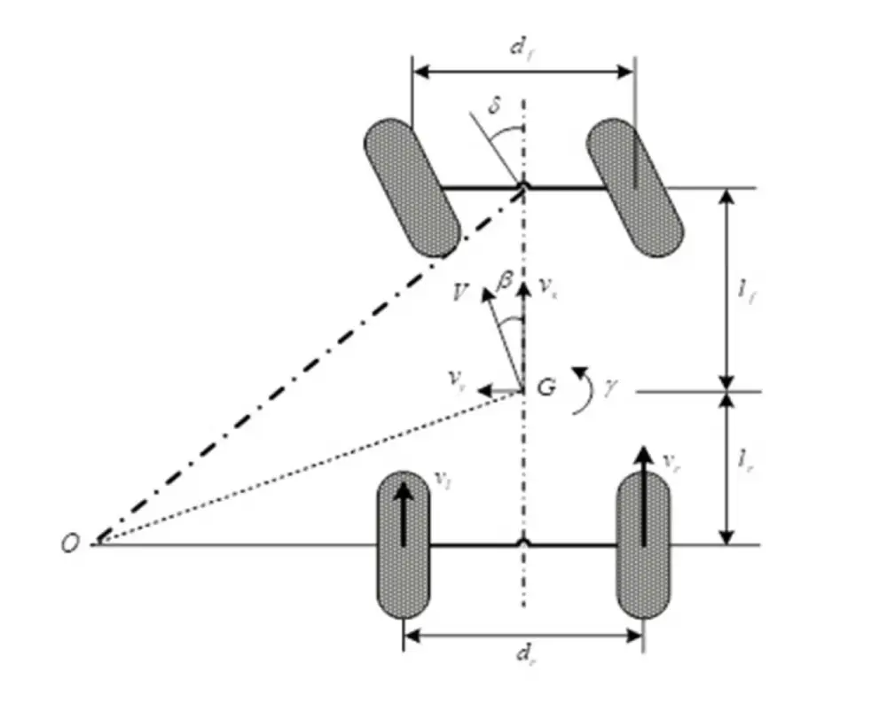
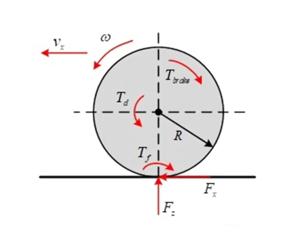
- Motor Torque-Based Control: This method uses the drive wheel motor torque as the control variable, instead of controlling wheel speed, allowing the wheels to rotate freely according to their load. Since each drive wheel can rotate independently, as long as the wheel-tire-road friction does not exceed the limit, the friction force on the road will balance the driving force. In the stable range of tire attachment characteristics, road friction is a monotonous function of slip ratio, meaning there is a direct correspondence between friction force and slip ratio.
As long as the motor torque does not exceed the attachment limit, the slip ratio remains within the stable region of tire attachment characteristics, and no differential issue arises, preventing wheel slip or drag. When the motor torque exceeds the friction limit, wheel slip will occur, and anti-slip control will be activated. This method can implement adaptive differential steering, where the control system outputs motor torque commands based on the vehicle’s motion state, and the wheel speed is determined by the tire force balance. This method, combined with anti-slip control, performs well for electronic differential functions, but its control algorithms become more complex as driving conditions change.
Increasingly, researchers prefer using motor torque as the control variable, which is closely linked to anti-slip research. Electronic differential research based on torque control and anti-slip technology is an integrated field, and many scholars worldwide have explored this from the perspective of vehicle dynamics control.
Current Development of Commercial Vehicles
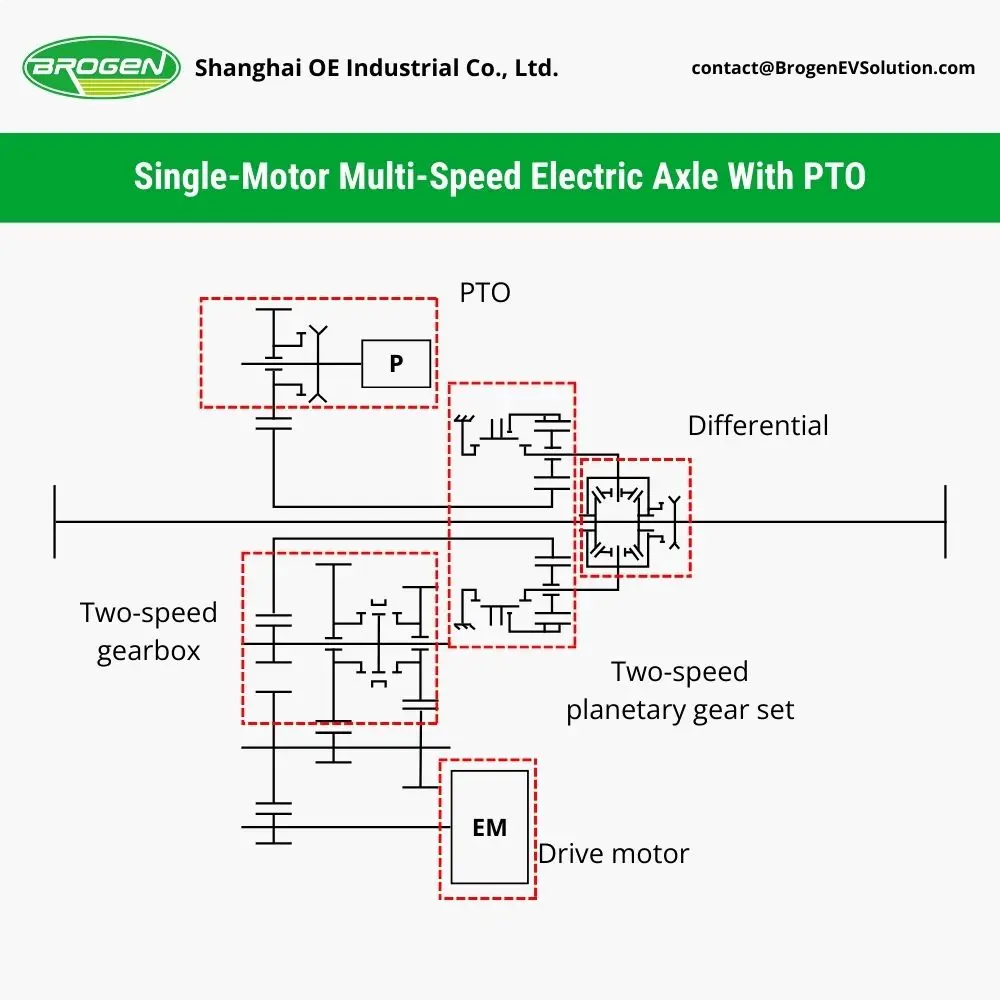
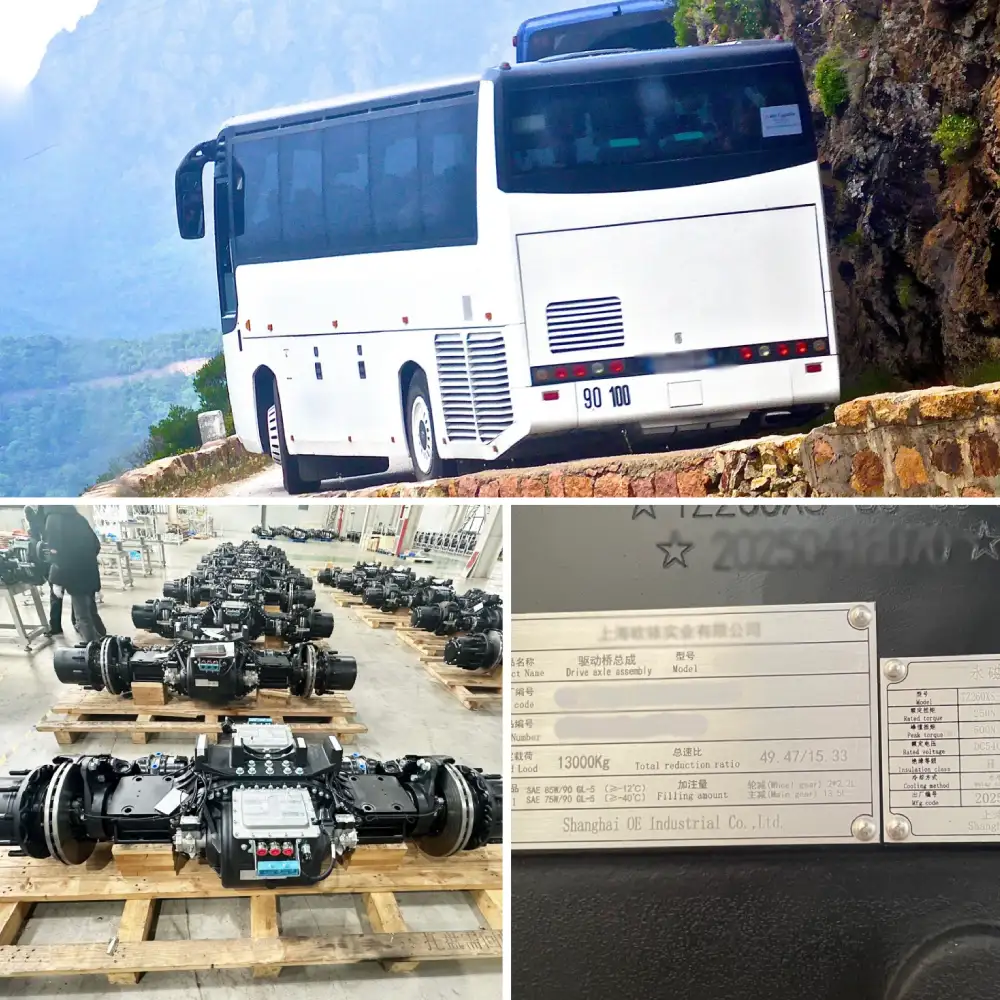
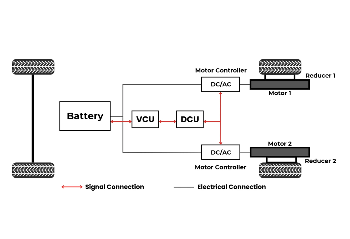
Compared to passenger cars, the advantages of distributed drive systems are more evident in commercial vehicles. First, the high integration of distributed drive systems enables low-floor, wide-passenger designs for city buses, facilitating quick and barrier-free transit, especially in large and medium-sized cities with an aging population, making distributed drive buses increasingly popular. Additionally, by eliminating mechanical differentials and drive shafts, lightweight independent suspension and single-tire configurations can be used, improving system efficiency. Lastly, distributed drive systems allow for independent, precise, and continuous control of drive and braking forces for each drive wheel, fully utilizing tire-road friction characteristics and enabling traction control, anti-lock braking, and stability control. Based on these advantages, the promotion of distributed drive technology in city buses is on the rise.
Engineering Development Process for Distributed Drive Electronic Differential Lock
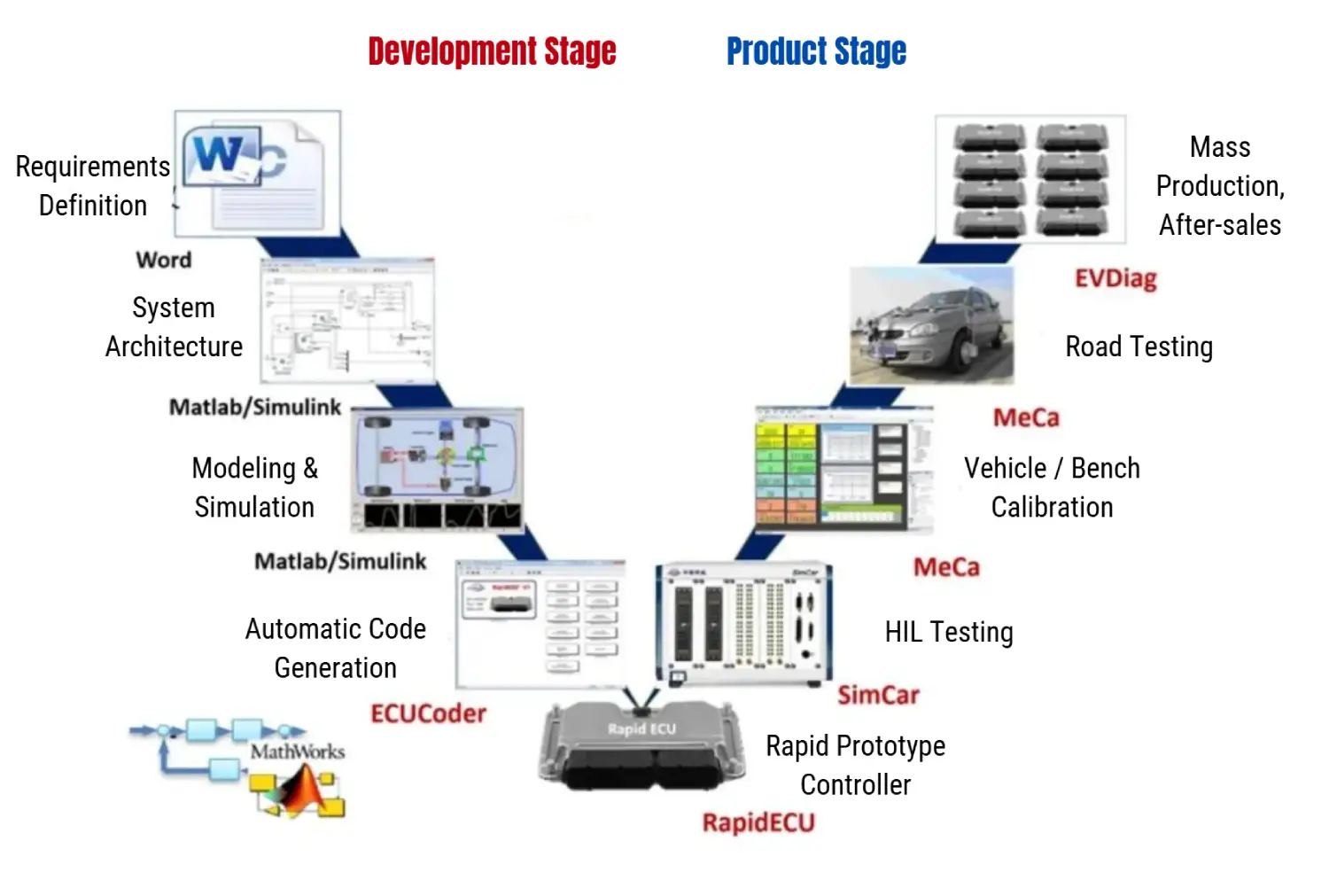
The engineering development process for distributed drive electronic differential control technology follows the V-model, from initial function definition and requirement analysis to final application and mass production. The V-model emphasizes collaboration and speed in software algorithm development, integrating algorithm implementation and verification, shortening the development cycle while ensuring high-quality software algorithms.
The development process consists of two phases: the software algorithm development phase and the product testing phase. At the start of software algorithm development, requirements are defined, including market demands and product functionalities. After understanding these requirements, designers can proceed with system architecture and product functionality design. The algorithm development team will then create models and simulations, using Matlab for algorithm design. Offline simulations, including model-in-loop and software-in-loop simulations, are performed before downloading the algorithm to rapid prototyping devices for online simulation and algorithm verification.
After this, the software-generated C code is tested with the ECU on a test bench. Once the software and hardware are tested, control parameters are optimized during real-world road testing. This includes calibrating the vehicle’s performance to its best state and conducting reliability tests over a set distance. After completing the above steps, the product can be mass-produced and launched into the market, with continuous feedback for algorithm optimization and upgrades. Each step in the process is crucial for ensuring reliable products and functionality.
Project Development Personnel, Timeline, and Budget
6.1 Personnel
Compared to traditional central drive systems, the development of distributed drive systems involves more complexity due to the harsh operating environment of the motors. This requires a broader range of expertise. For example, the development of the new energy system involves roles such as:
- 2 people for gearbox design
- 2 people for motor design
- 1 person for motor controller matching
- 1 person for power system performance and efficiency matching
- 2 people for vehicle control strategy development
- 1 person for vehicle calibration, etc.
In the chassis design, roles include:
- 1 person for axle design
- 2 people for suspension design
- 1 person for brake design
- 1 person for steering, etc.
The simulation team requires specialists for NVH (1 person), thermal transfer (1 person), and structural strength (1 person). Production-related tasks will require 2 people involved in process management. Additionally, a senior engineer (1 person) is needed for overall project integration, and a project manager (1 person) will be responsible for resource coordination and progress tracking. The total team size is estimated at over 21 members to ensure smooth project development.
6.2 Development Timeline
| Task Name | Duration | Details |
|---|---|---|
| Project Initiation | 2 months | Competitive product research, confirmation of product parameters, project initiation report review |
| Design Freeze (Components) | 6 months | Detailed component design, control strategy development, supplier confirmation |
| Prototype Production Completed | 2 months | Product assembly and debugging, control strategy simulation testing |
| Vehicle Performance Evaluation | 4 months | Motor calibration, test vehicle setup, program debugging, testing and optimization |
| Design Adjustments | 4 months | Addressing performance issues, product installation, and testing |
| Bench Reliability Testing | 4.5 months | Reliability and durability testing of components (axle, motor, gearbox, suspension) |
| Vehicle Reliability Testing | 6 months | 30,000-45,000 km road tests, 80,000 km tire wear tests |
| Project Adjustments and Line Optimization | 6 months | Design adjustments, production line resource matching, control strategy freeze |
| Project Completion | 2 months | Final project review, SOP handover to production team |
| Total | ~36.5 months |
Note: With prior development experience and strong technical oversight, the project timeline can be reduced by 6-9 months.
6.3 Budget
The development of a competitive distributed drive product requires significant investment in new components, with minimal off-the-shelf parts available. The development costs focus on personnel salaries, prototype investments, mold creation, and testing. Based on experience, a minimum investment of around 48 million RMB is required, with approximately 10 million RMB allocated for salaries, 3 million RMB for prototype costs, 12 million RMB for mold and tooling, 8 million RMB for testing, and 15 million RMB for production line setup.
In conclusion, each phase of developing a distributed drive product, from personnel planning and project management to testing and pre-production setup, involves a complex subproject. Supplier selection and collaboration require substantial investment, but the return on investment is uncertain. This is why, although many suppliers engage in R&D for such products, few achieve mass production.
How We Can Help?
At Brogen, we offer mature and stable EV systems and solutions tailored specifically for commercial vehicles, including buses and trucks. Our solutions integrate cutting-edge technology, such as our Electronic Differential Lock (EDL), to provide high efficiency, enhanced driving performance, and seamless integration into various vehicle types.
What sets us apart:
Proven EDS Technology: Our electronic differential solutions offer precise control over wheel torque and speed, ensuring smooth, reliable operation even under challenging conditions.
Specialized R&D Team: Our experienced engineering team has extensive expertise in electric drive systems, ensuring that our products are at the forefront of innovation and performance.
Customization for Commercial Vehicles: We understand the unique needs of commercial vehicle manufacturers, and our solutions are designed to optimize vehicle performance, reduce operating costs, and enhance overall efficiency.
Our expertise and commitment to innovation enable us to provide high-quality, reliable, and efficient solutions that meet the growing demands of the new energy commercial vehicle market. By partnering with Brogen, you can take advantage of the latest in EV technology, which will support your efforts in sustainable transportation and help you stay ahead of the competition.
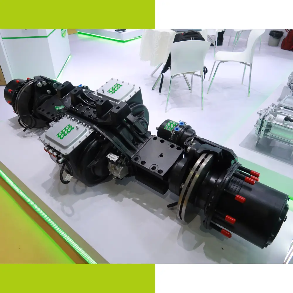
Distributed e-Axle for HCVs
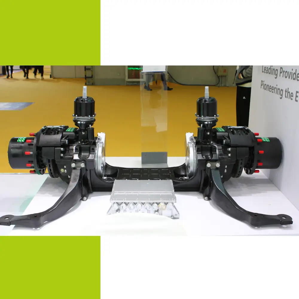
Distributed e-Axle for Public Transport
Contact Us
Get in touch with us by sending us an email, using the Whatsapp number below, or filling in the form below. We usually reply within 2 business days.
Email: contact@brogenevsolution.com
Respond within 1 business day
Whatsapp: +8619352173376
Business hours: 9 am to 6 pm, GMT+8, Mon. to Fri.
LinkedIn channel
Follow us for regular updates >
YouTube channel
Ev systems introduction & industry insights >