Mining Electrification Solutions: Electric Dump Truck System Design
1. Introduction
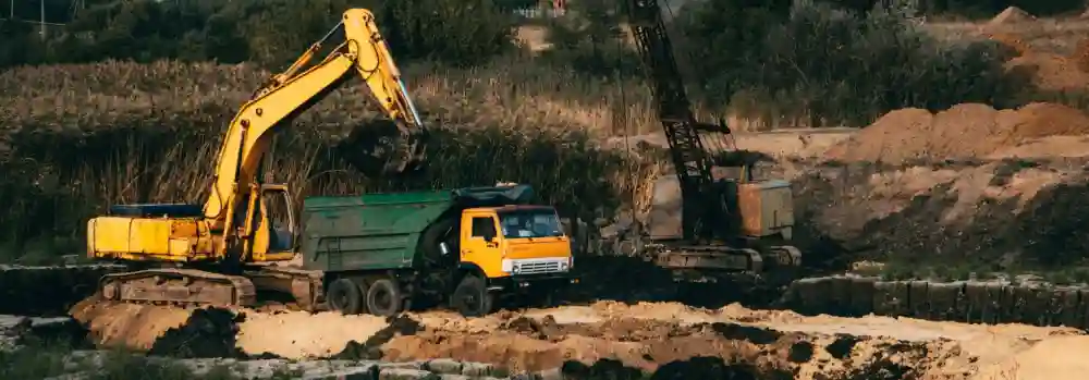
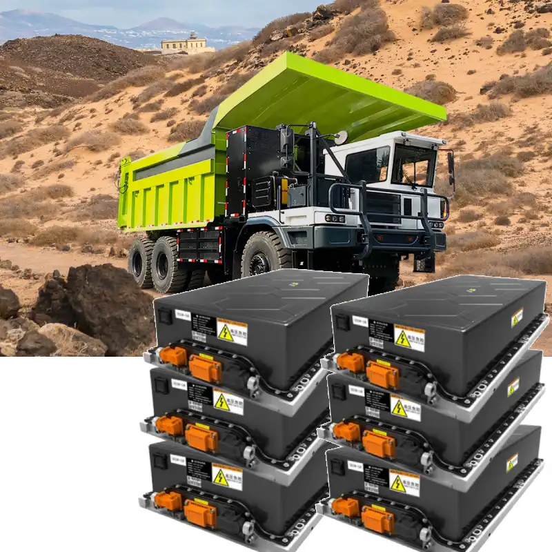
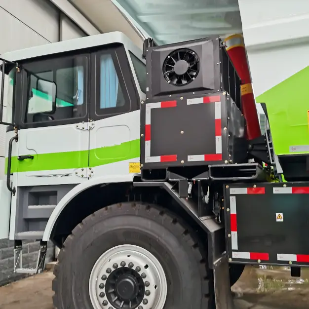
The electric dump truck is a specialized off-highway vehicle designed for short-haul material transport in industries such as mining, metallurgy, cement, water conservancy, and construction. Its working conditions are characterized by steep slopes, short routes, large load variations, fixed transport lines, and complex operating environments. Traditional diesel-powered dump trucks face several challenges in these conditions: high fuel consumption, elevated maintenance costs, and shorter service life.
By contrast, electric dump trucks replace diesel engines and manual transmissions with battery packs and electric drive motors. When traveling on flat roads or downhill, the motor operates in regenerative braking mode, converting braking energy into electricity to recharge the battery. This not only reduces wear on the mechanical brake system – improving safety and extending component life – but also increases vehicle range.
With fewer maintenance needs, high protection levels, and superior adaptability to harsh mining environments, electric dump trucks are becoming the preferred choice for heavy-duty operations.
2. High-Voltage System Architecture of Electric Dump Truck
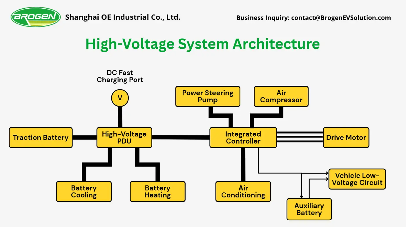
Electric dump trucks replace the conventional powertrain with a high-voltage system. The main high-voltage components include: traction battery, PDU, DC fast charging port, integrated controller, thermal management system, and other auxiliary high-voltage systems.
● Traction Battery
It’s the energy supply unit in an electric dump truck, providing electric power to all vehicle systems. When the battery is depleted, it also requires recharging. Therefore, the energy flow of the battery is bidirectional.
● High-Voltage Power Distribution Unit (PDU)
The PDU is a distribution hub for high-voltage power, supplying electricity to all components within the high-voltage system. For example, battery heating, charging circuits, and power distribution to the integrated controller. Inside the PDU are fuses, relays, and a pre-charge circuit for each controllable high-voltage loop.
Between the traction battery and the PDU, a Manual Service Disconnect (MSD) is installed. The MSD is a mandatory safety device that allows physical disconnection of the high-voltage circuit during battery servicing or vehicle maintenance. It ensures safe isolation of the high-voltage system and often incorporates fuse protection to enhance electrical safety and reliability.
● Thermal Management System
The thermal management system integrates both heating and cooling functions, maintaining the traction battery within its optimal operating temperature range to ensure safety, efficiency, and extended service life.
● Motor Controller and Drive Motor
The motor controller converts high-voltage DC from the integrated controller into three-phase AC to power the drive motor. It regulates motor torque and rotational direction, enabling smooth vehicle start, stop, forward, and reverse operations. Additionally, during braking or deceleration, the drive motor recovers kinetic energy, converts it into electrical energy, and feeds it back to the traction battery for extended range and efficiency.
● DC Fast-Charging Port
The DC fast-charging port delivers high-voltage direct current, which can be routed through the PDU directly to the power battery for rapid charging without additional processing.
● Integrated Controller
The integrated controller receives commands from the VCU and coordinates both the main drive system and auxiliary subsystems. Key auxiliary loads include the cab air-conditioning compressor, PTC heater, electro-hydraulic power steering pump, air compressor, and DC/DC converter.
The DC/DC converter steps down high-voltage DC from the traction battery to low-voltage DC to charge the auxiliary lead-acid battery. Compared with traditional distributed controllers, the integrated controller offers reduced size and footprint, optimizing vehicle layout. Minimizing high-voltage external wiring between discrete controllers reduces potential failure points, lowers costs, and enhances overall system reliability and safety.
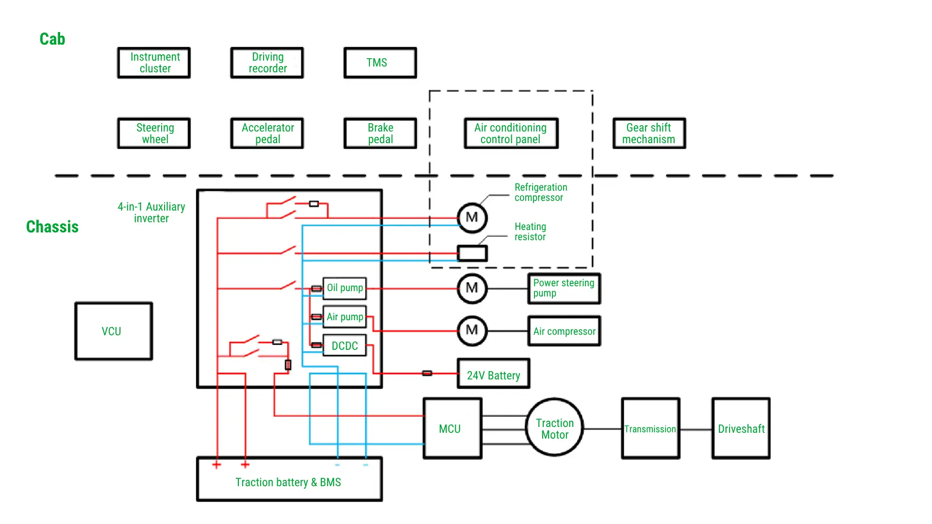
● Auxiliary High-Voltage Systems
- The electric A/C compressor and PTC heater serve as the core components of the HVAC system, delivering cooling and heating functions.
- The electric air compressor supplies high-pressure compressed air for the braking system.
- The electro-hydraulic power steering pump provides hydraulic assistance to the steering system.
3. Traction Battery Selection and Design
At present, mainstream electric vehicles generally adopt ternary lithium batteries or lithium iron phosphate (LFP) batteries. LFP batteries use lithium iron phosphate as the cathode material and graphite as the anode material. Compared with ternary batteries, LFP batteries offer the following advantages:
- High safety performance: The decomposition temperature of LFP is about 600°C. Even under high temperature or overcharge conditions, it does not undergo structural collapse, generate excessive heat, or form highly oxidative substances as ternary batteries do. In the event of a collision or short circuit, LFP batteries are also highly resistant to explosion.
- Long cycle life: The cell cycle life can reach up to 4,000 cycles, and around 3,000 cycles at the PACK level.
- Excellent high-temperature performance: Wide operating temperature range with strong thermal stability.
- Environmental friendliness: LFP batteries contain no heavy metals or rare metals, making them non-toxic and pollution-free.
These features make LFP batteries particularly well-suited for mining applications, where operating conditions are harsh, ambient temperatures vary widely, and safety requirements are stringent.
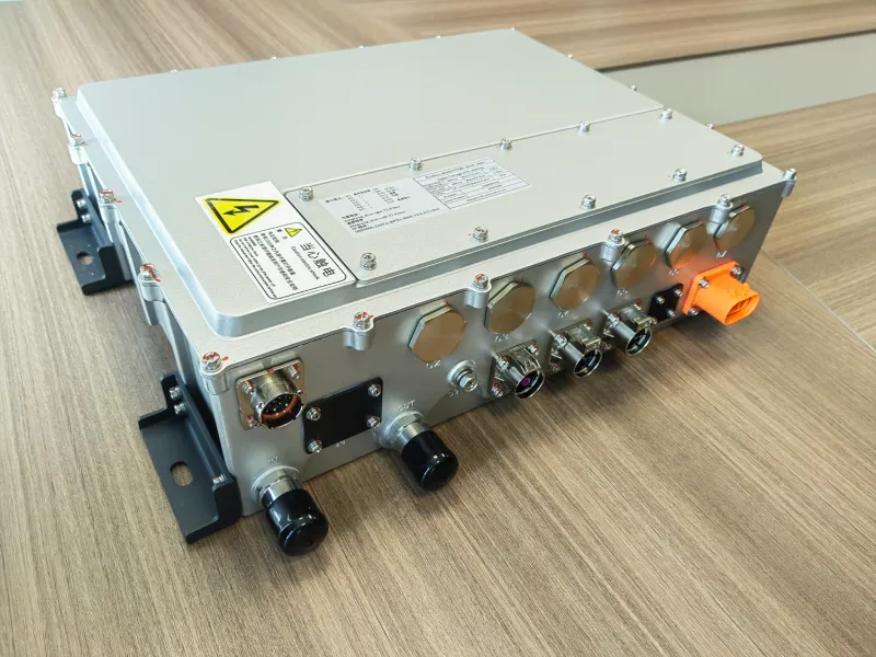
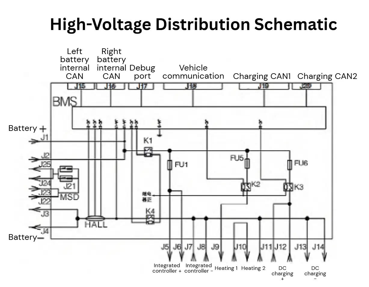
4. High-Voltage Power Distribution Unit (PDU) Design
The High-Voltage Power Distribution Unit (PDU) is responsible for distributing electrical power throughout the vehicle’s high-voltage system. Its function is similar to a fuse box in a low-voltage electrical system, primarily managing power distribution and providing overload and short-circuit protection for high-voltage circuits.
- Monitoring the total battery voltage and charge/discharge current.
- Monitoring battery status, including individual cell voltages and temperatures, module temperatures, and the temperature of the charging socket.
- Monitoring vehicle high-voltage connection status and insulation condition.
- Estimating the State of Charge (SOC) and State of Health (SOH) of the traction battery.
- Developing battery charging and discharging strategies.
- Controlling the battery thermal management system.
- Managing cell balancing to ensure consistency across individual cells.
- Diagnosing battery faults and executing corrective actions.
- Communicating with the vehicle’s VCU to respond to its control commands.
The internal high-voltage distribution layout of the PDU is illustrated below.
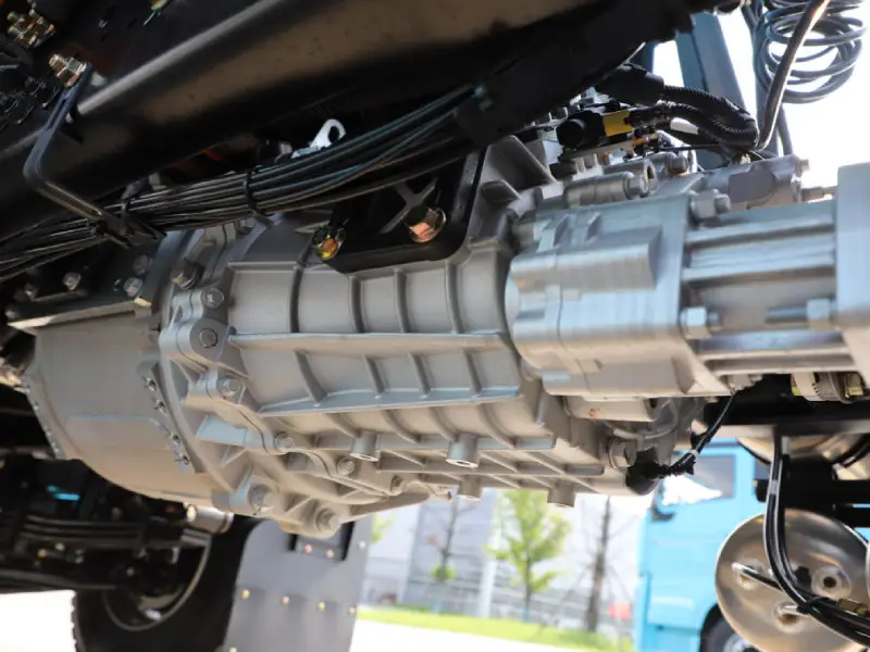
5. Electric Powertrain System Design for the Electric Dump Truck
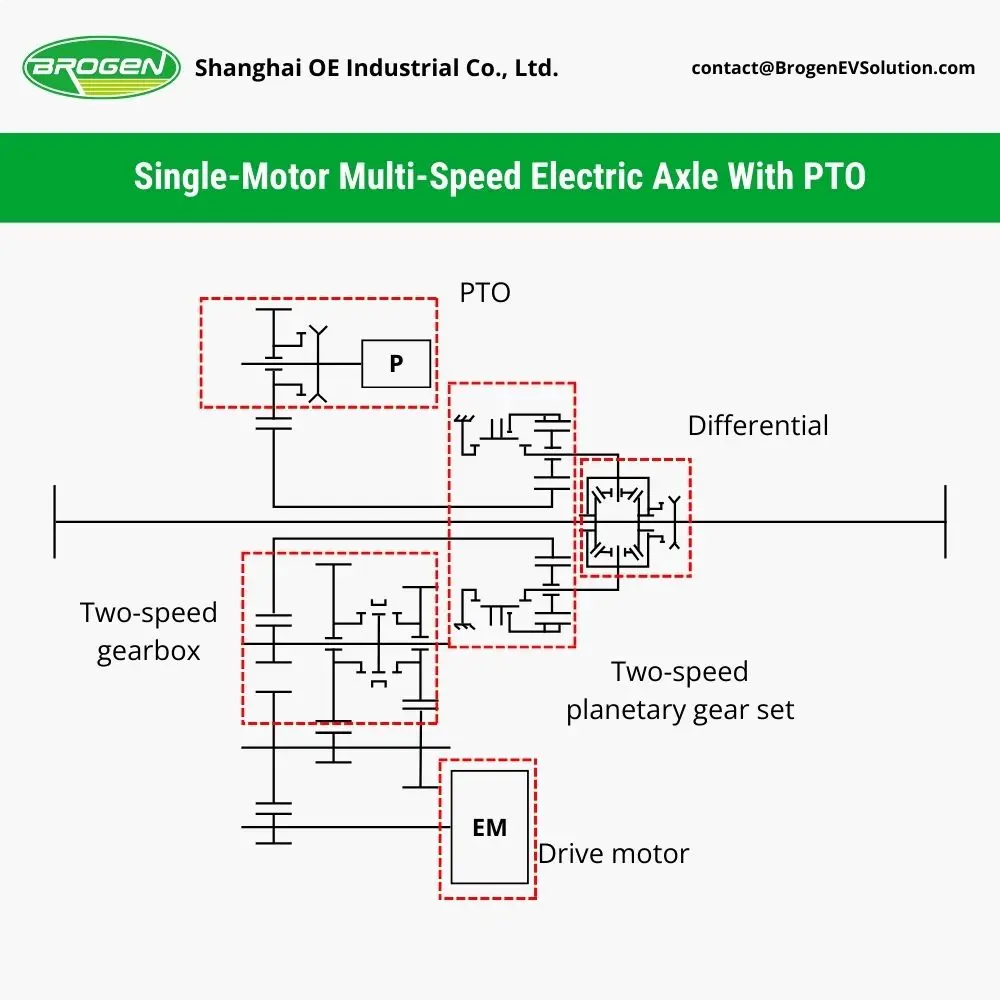
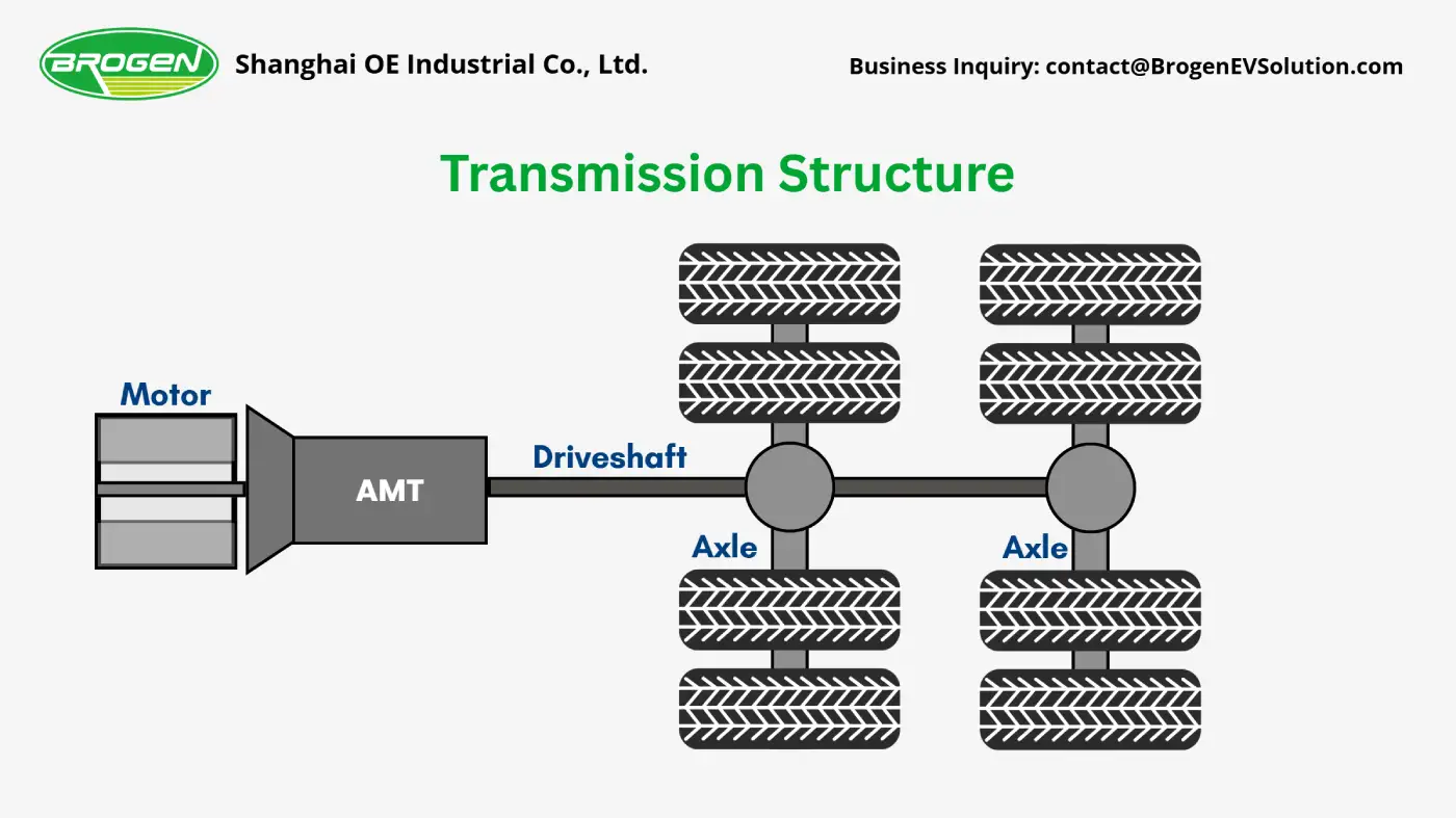
The vehicle employs a centralized drive motor + multi-speed AMT gearbox + rear axle reducer configuration. The drive motor is a high-power PMSM (e.g., Brogen’s 250kW/400kW motor). Compared with asynchronous motors, it offers higher operational efficiency, power density, and torque density. At low speeds, the motor can deliver high torque, facilitating vehicle start-up, while at high speeds, it maintains constant power output, enabling higher vehicle speeds.
Considering that wide-body dump trucks experience large load variations and steep gradients in mining operations, the e-powertrain uses a multi-speed AMT. This ensures that the drive motor operates continuously within its high-efficiency range while meeting vehicle performance requirements for climbing and acceleration.
The AMT gearbox employs clutchless, electronically controlled shifting technology. The VCU optimizes shift logic based on vehicle speed, accelerator pedal position, road gradient, and other parameters, automatically executing gear upshift and downshift. This results in smooth, impact-free gear changes. The absence of a clutch reduces gearbox failure rates and extends service life. It also minimizes the need for frequent manual shifting, reducing driver fatigue.
The e-powertrain’s layout is illustrated below.
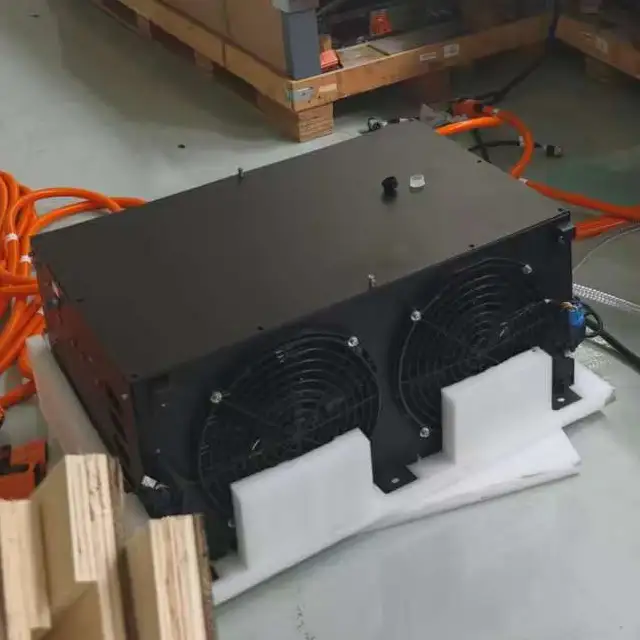
6. Battery Thermal Management System Design
For electric dump trucks, it’s essential to maintain the traction battery within an appropriate temperature range to ensure performance, safety, and longevity. The importance of the BTMS can be summarized as follows:
- Battery Capacity: LFP batteries exhibit poor low-temperature performance, with available capacity declining sharply in cold conditions. At -10°C, battery capacity drops by approximately 40%, and at -20°C, it can decrease by up to 60%.
- Battery Safety: Charging the battery at low temperatures can inhibit lithium-ion diffusion at the anode and reduce the conductivity of the electrolyte. This leads to slower intercalation and accumulation of metallic lithium on the anode surface, forming lithium dendrites that may pierce the separator and contact the cathode, causing internal short circuits and potentially severe safety hazards.
- Battery Lifespan: The optimal operating temperature range for the battery is approximately 10-30°C. Exposure to temperatures outside this range, whether too high or too low, accelerates battery degradation.
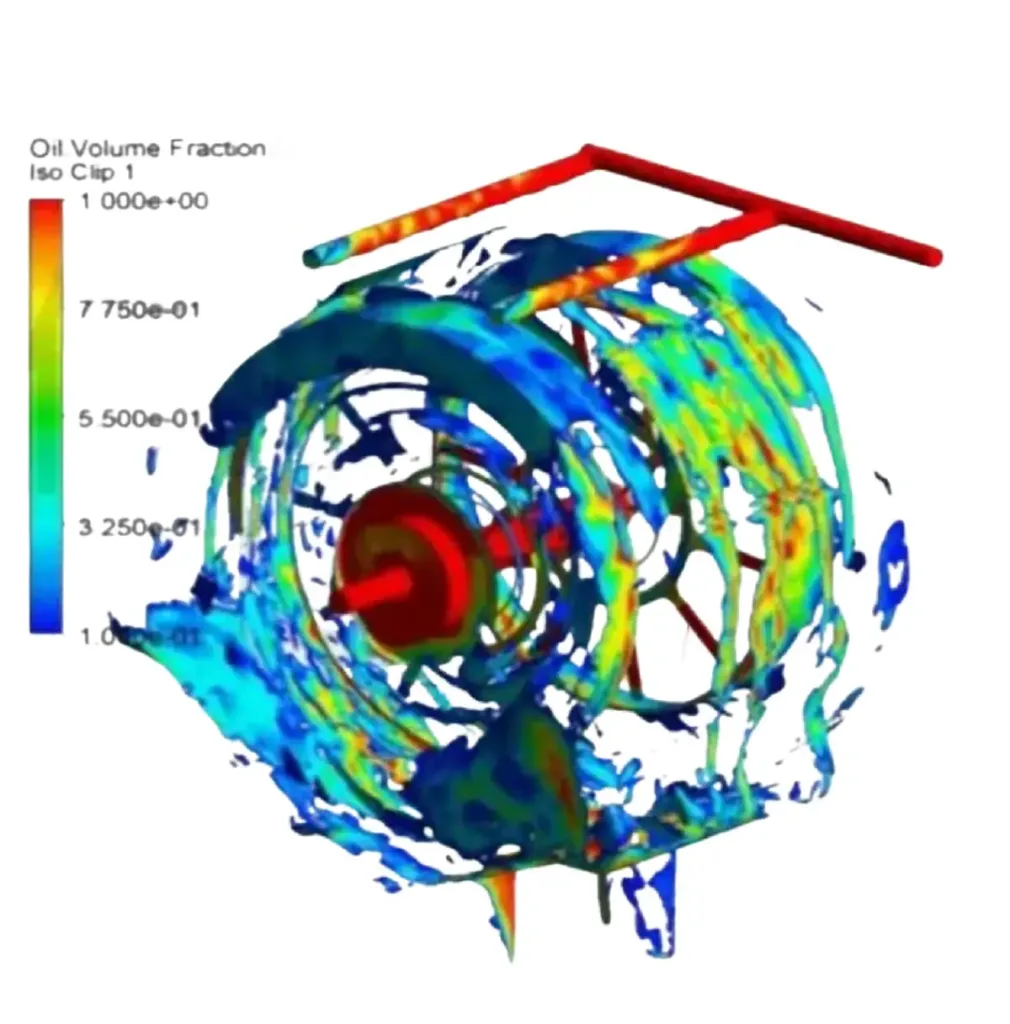
Considering that mining trucks experience high charge and discharge currents during operation, the BTMS adopts liquid-cooling technology for higher heat dissipation efficiency. By heating or cooling the coolant, the system maintains the battery temperature between 25°C and 35°C, ensuring optimal performance while limiting the temperature difference between individual cells to within 5°C. This guarantees uniform performance and extends the service life of the entire battery system.
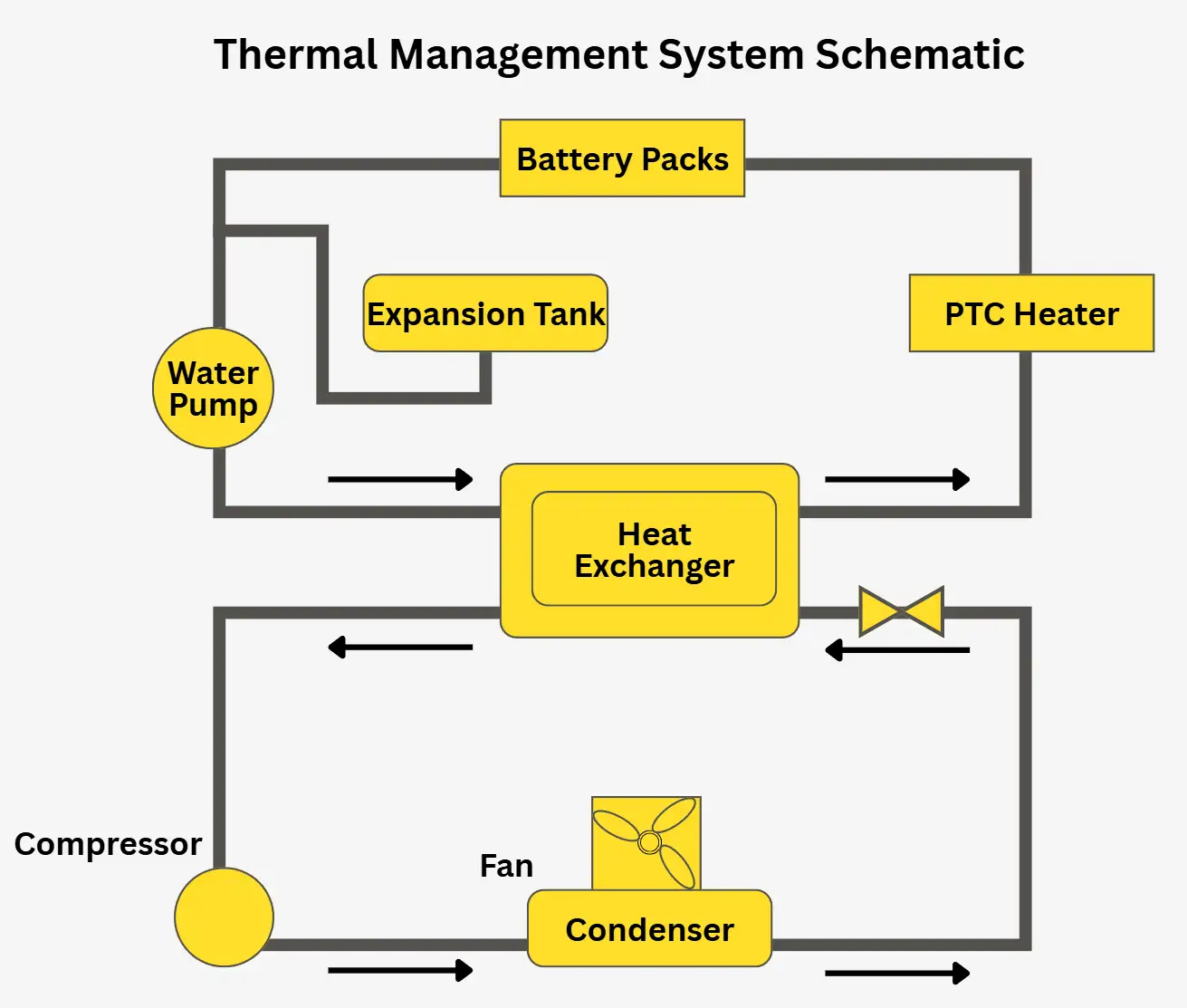
The BTMS employs a dual-flow heat exchanger design: one channel circulates the coolant, and the other channel carries the refrigerant. Odd-numbered layers contain coolant, while even-numbered layers contain refrigerant, enabling efficient heat exchange. After exchanging heat with the refrigerant, the coolant is cooled and then circulated through the battery pack to lower the battery temperature. When heating is required, the PTC heater activates to warm the coolant, which in turn heats the battery.
The schematic of the battery thermal management system is shown below.
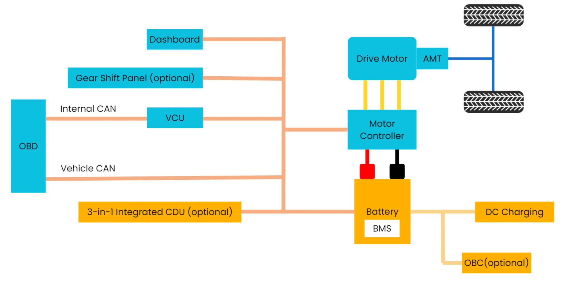
7. Vehicle CAN Network Design
CAN (Controller Area Network) is a distributed real-time communication protocol that enables multiple vehicle controllers to be networked together for unified control. With the increasing number of electronic control units (ECUs) in modern vehicles, CAN bus communication has become widely adopted in the automotive industry. Its key characteristics include:
- Simplified Wiring: CAN bus requires only two wires, and multiple nodes can be connected directly to the bus, eliminating the need for point-to-point wiring. This simplifies vehicle wiring design, reduces harness weight, and facilitates vehicle lightweighting.
- Differential Signal Transmission: Signals are transmitted in differential mode, providing strong resistance to external interference and enhancing the stability of vehicle electronic control systems.
- High Flexibility: Nodes can be easily added or removed, significantly improving the flexibility of system design.
- High-Speed Communication: CAN bus supports communication speeds up to 1 Mb/s, enabling fast data transfer and strong real-time performance.
- Fault Tolerance: In the event of severe errors at a node, the CAN protocol can automatically shut down that node’s output, ensuring that other nodes on the bus continue to operate without interruption.
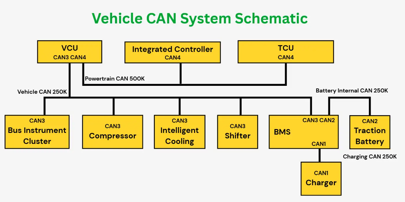
In a pure electric dump truck, the number of ECUs is high, and the control system requires large amounts of data to be transmitted in real time. Therefore, the vehicle CAN network is divided into multiple segments based on function, data transmission rate, and bus load requirements: charging CAN1, vehicle CAN3, powertrain CAN4, and battery internal CAN2.
The overall vehicle CAN communication network topology is shown below.
8. Vehicle Control Unit (VCU) Functional Design
The Vehicle Control Unit (VCU) is the core component of an electric vehicle. The smoothness of vehicle operation, energy efficiency, and overall reliability are closely tied to the effectiveness of the VCU’s control. The main functions of the VCU can be summarized as follows:
- High-Voltage Power-Up and Power-Down Control
- Driver Intent Recognition, using signals from the accelerator, brake, and gear position to interpret driver commands
- Hill Start Assist and Anti-Rollback Function
- Shift Control Strategy for Flat and Inclined Roads
- Downhill Cruise Control
- Vehicle Power Output and Energy Recovery Strategy Management
- Auxiliary System Control
- Fault Diagnosis and Hierarchical Handling
- Vehicle Status Monitoring and Driver Feedback via Display Systems
- Customizable Vehicle Function Settings
- Coordination Control Among Various Component Controllers
- Optimization of Vehicle Energy Efficiency and Driving Comfort
- Real-Time Data Interaction and Remote Vehicle Monitoring
8.1 High-Voltage Power-Up and Power-Down Process
High-Voltage Power-Up Process
- The vehicle switches on low-voltage “ON” mode, awakening all control units via the VCU.
- Upon receiving the key start signal, the VCU closes the main negative relay. After detecting its closure, it waits 500 ms before closing the pre-charge relay to perform pre-charging.
- Once pre-charging is complete, the main positive relay is closed within 1 s.
- After closing the main positive relay, the system waits 500 ms and then opens the pre-charge relay. High-voltage power-up is complete, and a Ready signal is sent to indicate HV activation.
High-Voltage Power-Down Process
- After the ON signal disappears (lasting 500 ms), the BMS waits for a shutdown command from the VCU. If no command is received within 25 s, the BMS will force shutdown and enter sleep mode.
- The VCU sends the shutdown command, disabling all high-voltage components. Once the bus current drops below 5 A, the main positive and negative relays are opened sequentially.
- Fast discharge is activated. When the bus voltage drops below 36 V, high-voltage shutdown is complete.
- After 500 ms, the VCU enters sleep mode.
8.2 Drive Controller Strategy
Electric dump trucks require tailored driving strategies based on real-world operating conditions to maximize efficiency and minimize energy consumption. When responding to accelerator and brake inputs, the VCU adjusts control based on current vehicle status, selecting appropriate torque curves and torque response times to deliver optimal torque.
8.3 Energy Recovery Control Strategy
Energy recovery refers to regenerative braking, where the motor converts kinetic energy into electrical energy and feeds it back to the power battery while generating braking torque. Safe output of braking torque is constrained by:
- Maximum battery charging capacity
- Individual cell status and overall SOC
- Motor braking capability
- Minimum vehicle speed
8.4 Fault Hierarchy and Handling Strategy
Faults are classified and handled according to severity to ensure vehicle safety, with three levels of fault response:
- Low-Level Fault: Audible and visual warnings on the instrument cluster; vehicle continues normal operation.
- Medium-Level Fault: Audible and visual warnings; vehicle operates at 50% power, with the dashboard indicating reduced performance.
- High-Level Fault: Audible and visual warnings; vehicle is stopped, high-voltage is cut off (e.g., insulation failure, short circuit, collision).
The VCU control strategy is developed using a complete V-process strategy development model, employing interactive algorithm development and experimental validation to ensure safety at every stage. A combination of data-driven and model-based approaches allows for customized, intelligent strategies tailored to specific operating conditions and environments, enhancing both adaptability and safety.
9. Conclusion
After adopting a fully electric powertrain, dump trucks produce zero tailpipe emissions, including carbon dioxide (CO₂), nitrogen oxides (NOₓ), and particulate matter, effectively eliminating environmental pollution. Electric vehicles also do not require engine oil, oil filter, or air filter replacements, reducing maintenance time and costs while improving equipment availability.
Operating costs are significantly reduced, with electricity expenses much lower than conventional fuel consumption. The total cost of ownership for electric dump trucks can be reduced by 60%–80%, providing substantial economic benefits to operators.
In particular, under heavy-load operating conditions, regenerative braking allows the vehicle to recover kinetic energy and recharge the power battery. This not only extends vehicle range but also reduces the frequency of mechanical braking, prolonging the service life of braking system components.
With the continuous advancement of battery technology, fully electric dump trucks are expected to gradually replace traditional diesel-powered mining trucks, offering cleaner, safer, and more cost-effective operations.
Brogen EV Systems for Electric Dump Trucks
At Brogen, we provide proven and reliable EV systems for electric dump trucks, including:
- Motor+Multi-speed AMT e-Powertrain – a system already deployed at scale in commercial vehicles from leading OEMs. Learn more here: https://brogenevsolution.com/250-kw-400-kw-electric-motor-for-heavy-duty-truck/
- Tailored EV battery solutions – covering battery packs, BMS, BTMS, and PDU, designed for durability and safety in demanding mining environments. Learn more here: https://brogenevsolution.com/ev-battery/
- Auxiliary systems, including EHPS, air brake compressors, and auxiliary inverters for HCV electrification. Discover our HCV solutions here: https://brogenevsolution.com/heavy-duty-vehicle-electrification-solutions/
- Business inquiry: contact@BrogenEVSolution.com
Contact Us
Get in touch with us by sending us an email, using the Whatsapp number below, or filling in the form below. We usually reply within 2 business days.
Email: contact@brogenevsolution.com
Respond within 1 business day
Whatsapp: +8619352173376
Business hours: 9 am to 6 pm, GMT+8, Mon. to Fri.
LinkedIn channel
Follow us for regular updates >
YouTube channel
Ev systems introduction & industry insights >