Industry Insight

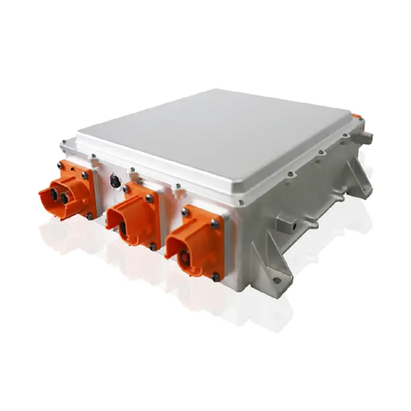
3-in-1 on-board charger (OBC) + DCDC+ PDU onboard charger
Industry Insight

Everything You Need to Know About The On Board Charger for Electric Vehicles

Everything You Need to Know About The On Board Charger for Electric Vehicles What is an on-board charger? An On Board Charger (OBC) is a device that converts AC power into DC power. It transforms the AC voltage from charging stations into the DC voltage required by the battery. OBCs are installed in electric vehicles (EVs) and plug-in hybrid electric vehicles (PHEVs). They enable these vehicles to be charged using AC power from residential or public charging stations. The output power of an OBC typically ranges from 3.3 kW to 22 kW. A significant advantage of OBCs is their ability to charge electric vehicles using standard household outlets. What are the different methods of charging an electric vehicle? Electric vehicle charging stations can be broadly categorized into two types: AC charging stations and DC charging stations. AC Charging Stations As the name suggests, AC charging stations provide alternating current (AC) from the electrical grid to electric vehicles. The onboard charger then converts the AC to direct current (DC) to charge the vehicle’s battery. These stations, also known as Level 1 and Level 2 chargers, are used in residential and commercial applications. The advantage of AC charging stations is that the OBC can adjust the voltage and current according to the vehicle’s needs. This eliminates the need for the charging station to communicate with the electric vehicle. However, the disadvantage is their low output power. It results in longer charging times. AC power from the grid is delivered directly to the OBC via an Electric Vehicle Supply Equipment (EVSE), which then converts it to DC and charges the battery via the Battery Management System (BMS). DC Charging Stations DC chargers take AC power from the grid and convert it to DC, bypassing the OBC to charge the battery pack directly. These chargers typically deliver high voltages up to 600V and currents up to 400A. Unlike AC chargers, which take 8-16 hours to charge a vehicle, DC charging stations can fully charge an electric vehicle in approximately 30 minutes. These stations are also known as Level 3 chargers, with the chargers referred to as DC Fast Chargers (DCFC) or Superchargers. The main advantage of DC chargers is their fast charging time. However, they are technically complex and need to communicate with the electric vehicle to charge it efficiently and safely. As shown in the typical DC charging system diagram, the EVSE bypasses the OBC and delivers DC power directly to the battery pack. The standard capacity of a DC charging station ranges from 50 kW to 300 kW. It’s more than 6 times the capacity of a single-phase on-board charger. However, AC charging through the OBC has less impact on the battery and minimizes battery aging. What are the functions of the onboard charger? The primary function of the OBC is to manage the charging process from the power grid to the vehicle’s battery. The OBC is designed to charge the battery as quickly as possible while minimizing battery degradation. It offers two charging methods: constant current charging and constant voltage charging. Constant current charging: this method charges the battery faster, but cannot fully charge the vehicle. Constant voltage charging: also known as trickle charging, this method charges the battery more slowly but with greater control, allowing the vehicle to reach a full charge. To optimize charging speed, the OBC uses constant current charging at the beginning of the charge cycle and switches to constant voltage charging toward the end. The OBC also plays a critical role in the bi-directional charging mode available in some vehicles. This capability allows it to convert DC power from the high-voltage battery pack back to AC power, supporting AC loads (Vehicle to Load, V2L), grid power (Vehicle to Grid, V2G), and even home power (Vehicle to Home, V2H). Hardware architecture of the OBC The OBC primarily consists of the following hardware components: Input Voltage Measurement Circuit: Measures the input voltage to control the conversion circuit. Input Filter: Suppresses internal noise or noise from external devices. Full-Wave Rectification Circuit: Converts AC voltage to DC voltage. Power Factor Correction (PFC) Circuit: Improves power efficiency degraded by waveform phase shifts. Voltage Conversion Circuit: Converts voltage using components such as an isolation transformer and field-effect transistor (FET) switches. Output Filter: Suppresses noise generated internally. Output Voltage Measurement Circuit: Measures the output voltage to control the conversion circuit. Control Circuit: Manages the conversion circuit and other components. DC/DC Converter: Provides power to the control circuit. Communication Interface: Facilitates communication with external devices. What are the trends and challenges in OBC development? The OBC is a critical component for both battery electric vehicles (BEVs) and plug-in hybrid electric vehicles (PHEVs). As the number of electric vehicles increases, the number of vehicles equipped with OBCs will also increase. At the same time, more electric vehicles will be equipped with DC fast charging capabilities.Key trends and challenges in OBC development include: Adaptation to 800V High-Voltage Platforms: OBCs will be compatible with these high-voltage systems. Increased Output Power: As 800V platforms become more common and battery capacities grow, OBCs will need to provide higher output power. Future OBCs will need to feature high voltage (high withstand voltage), high current, low loss, high heat resistance, and compact size. Bidirectional Charging Capability: OBCs will need to support bidirectional charging, allowing the conversion of DC power from high-voltage battery packs into AC power to support external AC loads. Use of Discrete High-Voltage Components: These components will be widely used in OBCs to enhance performance. Increased Power Requirements: The trend towards fast charging will significantly increase the power requirements of OBC topologies. Our On Board Charger Systems Engineered for top-tier power conversion efficiency and remarkable power density, our chargers cover a broad power spectrum, ranging from 3.3 kW to 40 kW. Whether you’re driving a passenger car, bus, van, or LCV, or require upfit power supply for specialized vehicles, our comprehensive solutions ensure seamless integration and optimal performance.  Applicable for both PHEV and BEV Wide input range, 1 phase
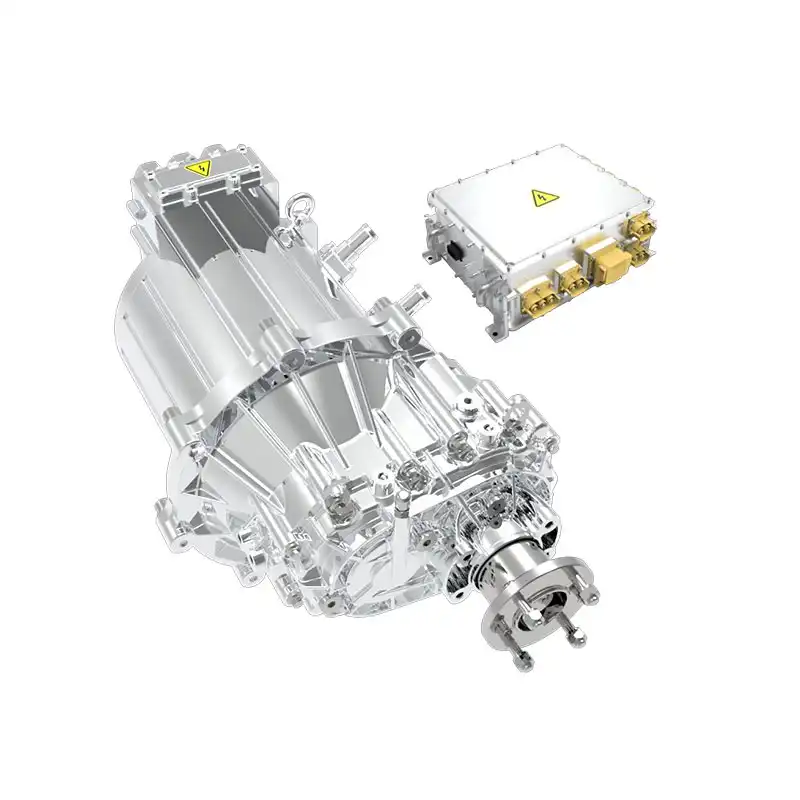
Brogen epowertrain-motor 100kW Electric Motor
Industry Insight, Light Commercial Vehicles

What Are The Benefits of Direct Drive System for Electric LCVs?

Two Major E-Powertrain Solutions for LCVs Electric power has become the primary driving force for new energy light trucks. These trucks typically employ two main power layouts: one utilizes a traditional drive motor paired with a gearbox and rear axle, while the other employs a combination of a motor and an electric drive axle. Initially, many automakers adopted the former approach to capitalize on emerging opportunities driven by policies and market demands. This involved directly modifying the architecture of conventional fuel-powered light trucks to create pure electric models, maintaining consistency with traditional fuel-based layouts. Developing an entirely new platform for new energy light trucks entails significant investments in manpower and finances, along with lengthy product validation processes. The “gas-to-electric” conversion model streamlines this process by simply replacing the original engine and transmission assembly with a motor and single-stage reducer. This not only reduces development time but also simplifies post-vehicle maintenance, resulting in lower costs. Moreover, the motor + reducer + rear axle combination closely resembles the power structure of diesel vehicles. The electric drive axle represents a novel technical solution that integrates components like the motor, reducer, and differential, enabling the axle to generate power output. Its major advantages lie in reducing vehicle weight and significantly increasing chassis space due to its high integration, thereby enhancing overall efficiency. Currently, traditional “gas-to-electric” new energy LCVs remain the preferred choice for EV builders due to their lower procurement and maintenance costs. Although they may be less technologically advanced than electric LCVs utilizing e-axle technology, their minor modifications to traditional power layouts ensure stronger reliability and stability by retaining the original vehicle structure. Brogen’s Direct Drive System for EV LCVs At Brogen, we offer both direct drive systems and electric axle systems. For our direct drive motor systems, in addition to single motor + controller systems, we also offer high-speed motor + controller + reducer systems, available in both high voltage and low voltage platforms. MCU, DCDC, Brake DCAC, Steering DCAC, and PDU functions are integrated into the high-voltage controller. Benefits include Example Configurations Motor + Controller Motor + Gearbox + Controller More EV Systems for LCVs Contact Struggling to find the perfect EV solution for your project? No need to fret! Simply fill out the form below, and we’ll tailor a solution to suit your needs. Alternatively, you can reach out to us directly at contact@brogenevsolution.com. Rest assured, we strive to respond promptly within 2 business days to ensure the seamless progress of your EV program. Let’s work together to make your electric vehicle vision a reality!

800V high voltage platform for electric vehicles
Industry Insight

Understanding the 800V High Voltage Platform in Electric Vehicles

Recently, various new energy vehicle companies have been vigorously promoting the charging speed of electric cars as one of their key selling points: 5 minutes of charging for 200 kilometers, 12 minutes for 500 kilometers. And among them, the 800V high-voltage platform is repeatedly mentioned. What is the 800V High Voltage Platform? 800V is a relatively broad term. It does not mean that the entire high-voltage electrical system of the vehicle can always reach 800V. Instead, it’s an average. The voltage range of the entire vehicle is within 550V to 950V, which can be called an 800V high-voltage platform. Currently, most new energy vehicles use a 400V platform, with the voltage range of the entire vehicle electrical system between 230V and 450V. The mainstream 800V high-voltage platforms currently available in the market mainly consist of three types: the first type is full-range 800V, where all of the vehicle’s electrical systems, such as motors, batteries, controllers, air conditioners, DCDC, etc., support 800V; the second type is key components supporting 800V, such as the electric drive system and battery supporting 800V, while other components such as the air conditioner still use 400V; the third type is only the battery supporting 800V fast charging, while other components remain at 400V. In fact, the 800V high-voltage platform concept wasn’t new in 2023. As early as 2019, Porsche introduced the first production model, the Taycan, with an 800V high voltage platform. However, due to its high price, the 800V platform was once almost a luxury car-only configuration. By 2023, many 800V high-voltage platform vehicles have flooded the market, intense competition has driven prices even lower, and more consumers are now considering whether a vehicle has an 800V platform as an important purchase consideration. What are the benefits of the 800V high-voltage platform? The reason why automakers choose to upgrade to the 800V high-voltage platform is twofold: on the one hand, it can significantly improve the charging and recharging speed, and on the other hand, because the 800V high-voltage platform can reduce energy loss compared to the 400V volt platform, it can indirectly improve the vehicle’s range. However, the energy loss advantage of the 800V high-voltage platform is not very significant. This is because currently the highest efficiency of motors on 400V platforms can already reach about 97 to 98%. The room for improvement with the 800V high voltage platform is quite limited. If the 400V platform is well optimized, the energy loss can still be reduced. That’s why most car manufacturers have not promoted this aspect very much. In terms of charging speed, the advantage of the 800V high-voltage platform becomes clear. Power = Voltage x Current (P = UI). To increase charging power, you either increase current or voltage. However, there aren’t many automakers currently choosing to increase charge power through high current schemes, Tesla being one of the few. The biggest drawback of high-current systems is heating. As the current increases, the heat generated by the entire system increases geometrically, leading to overheating of high-voltage harnesses and battery packs. From an energy consumption perspective, heating increases the energy dissipated in the system. From a safety perspective, battery pack overheating also increases safety risks. In comparison, most automakers currently choose to increase voltage to solve charging efficiency issues. By increasing the voltage to achieve the same charging power, not only does the charging speed increase, but the current is also reduced accordingly, reducing the heat generated by the harness and battery. It also allows the use of thinner wire harnesses. What are the challenges of the 800V high voltage platform? However, whether the 800V high voltage platform can be used for fast charging during the charging process depends not only on whether the vehicle itself supports 800V, but also on the cooperation of the charging stack. Currently, there are relatively few 800V chargers on the market. However, some models are equipped with on-board voltage boosting systems that increase the charging voltage to 800V during the charging process, ultimately achieving fast charging. Inquiry: contact@brogenevsolution.com

blade battery solution from brogen ev solutions
Industry Insight, Technologies

What is Blade Battery? New EV Battery Technology

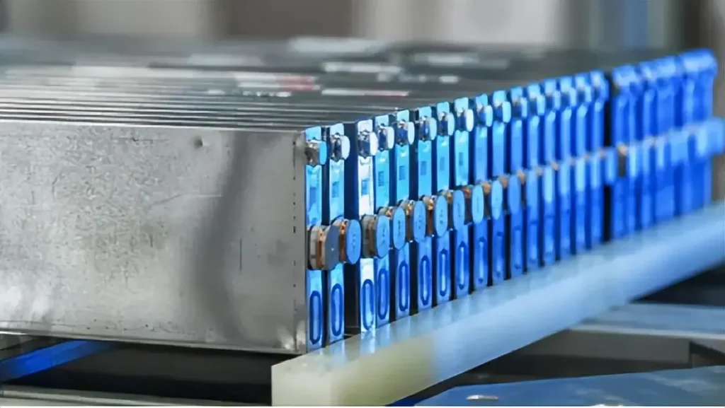
What is a blade battery? The blade battery is a lithium iron phosphate battery for electric vehicles. The battery cell has a special design with a common length of 96 cm and width of 9 cm, so it’s like a blade and can be inserted into the battery pack. While the standard LFP battery contains the structure of cell, module, pack, the design of the blade battery pack eliminates the battery module, which saves more space and thus greatly increases the space utilization and power density. When assembling battery packs with blade batteries, the inherent strength of the blade battery is leveraged to reduce the size of crossbeams and other components within the battery pack. Under random vibration loads, the deformation of the module is significant, while the deformation of the blade battery cells is minimal. For non-module battery packs, by modifying the structure of the battery pack, the rectangular batteries are arranged vertically and inserted into the pack, simplifying the battery pack structure and improving the utilization of internal space. What about the safety ? The blade battery successfully passed the nail penetration test and maintained a low surface temperature with no smoke or fire emissions. But its safety credentials go beyond that. The battery was tested in seven safety dimensions, including internal and external short circuits, overcharging, collisions, high pressure, connections and hazardous gas assessments. It also successfully passed collision simulation and crush tests. How is the performance? In terms of the performance of the blade battery, its high energy density provides enhanced endurance, with a maximum charging power of more than 230 kW. A mid-size vehicle equipped with BYD’s blade battery can easily exceed 700 km in range. In addition, the battery pack uses a wide-temperature efficient heat pump system and direct cooling and heating technology, which enables rapid temperature rise at low temperatures to meet driving demands. What are the advantages? The cost-saving aspect of the Blade battery is remarkable. As the main focus of development in the new energy vehicle sector shifts from simply increasing range to safer and smarter solutions, the lower cost advantage of lithium iron phosphate becomes increasingly important. By consistently reducing costs, the blade battery solution improves volume utilization by 50%, reduces component costs by 45%, and lowers overall costs by over 30%. What are the applications? In terms of applications, the Blade battery is not limited to passenger cars; it is also suitable for electric buses, vans, light-duty trucks, and heavy-duty trucks. For example, a light-duty truck equipped with a 45 kWh Blade battery pack can travel up to 280 kilometers on a single charge, making it ideal for urban delivery applications. Our blade battery solutions Our Blade battery solution ranges from 10 kW to 900 kW to meet the energy needs of different commercial vehicles. It also uses an intelligent Battery Management System platform that covers both low and high voltage. To learn more about our blade battery solutions, click the link here to view our blade battery catalog. You can also send your inquiry directly to our email and our experts will contact you to discuss how we can power your fleet. Inquiry: marketing@oe-autoparts.com

axial-flux-motor-faq from brogen ev solutions
Industry Insight, Technologies

Axial Flux Motors – Frequently Asked Questions (FAQ)

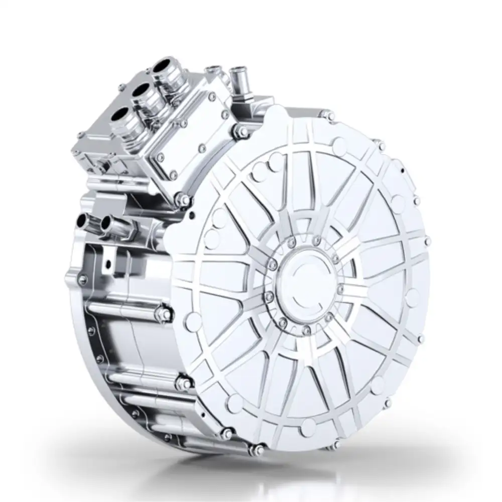
What are Axial Flux Motors? Axial flux motors differ from a radial flux motor in that its magnetic flux direction is axial, with current-carrying conductors arranged radially. Both the stator and rotor cores have a disc-like structure. What are the advantages / benefits? In situations with the same power,they have a smaller volume and lighter weight. For instance, our axial flux motor weighs and occupies approximately half the space of a traditional radial flux motor, resulting in higher power and torque density. Why they aren’t popular? While radial flux motors are well understood, and manufacturing methods are well-established, axial flux motors face significant challenges in design and production. The gap between the stator and rotor, known as the air gap, is crucial in the motor’s magnetic circuit. Axial flux rotor lying flat on the stator significantly increases the air gap area, demanding high precision in surface smoothness and gap uniformity. This translates to stringent requirements for manufacturing and assembly precision, leading to high production costs and low production flexibility. The manufacturing difficulty also hinders the scalability of axial flux motors, resulting in a smaller market capacity with insufficient component matching. However, our axial flux motor has overcome these challenges, achieving mass production and undergoing 15,000 km of safety testing in vehicles like buses and heavy trucks, ensuring stability and safety. What are the applications of them? They find application in various scenarios: What electric vehicles are they suitable for? They can be applied in various electric vehicles, including: Inquiry: contact@brogenevsolution.com Contact

axial flux motor
Industry Insight, Technologies

Axial Flux Motor for Electric Vehicles: A Comprehensive Overview

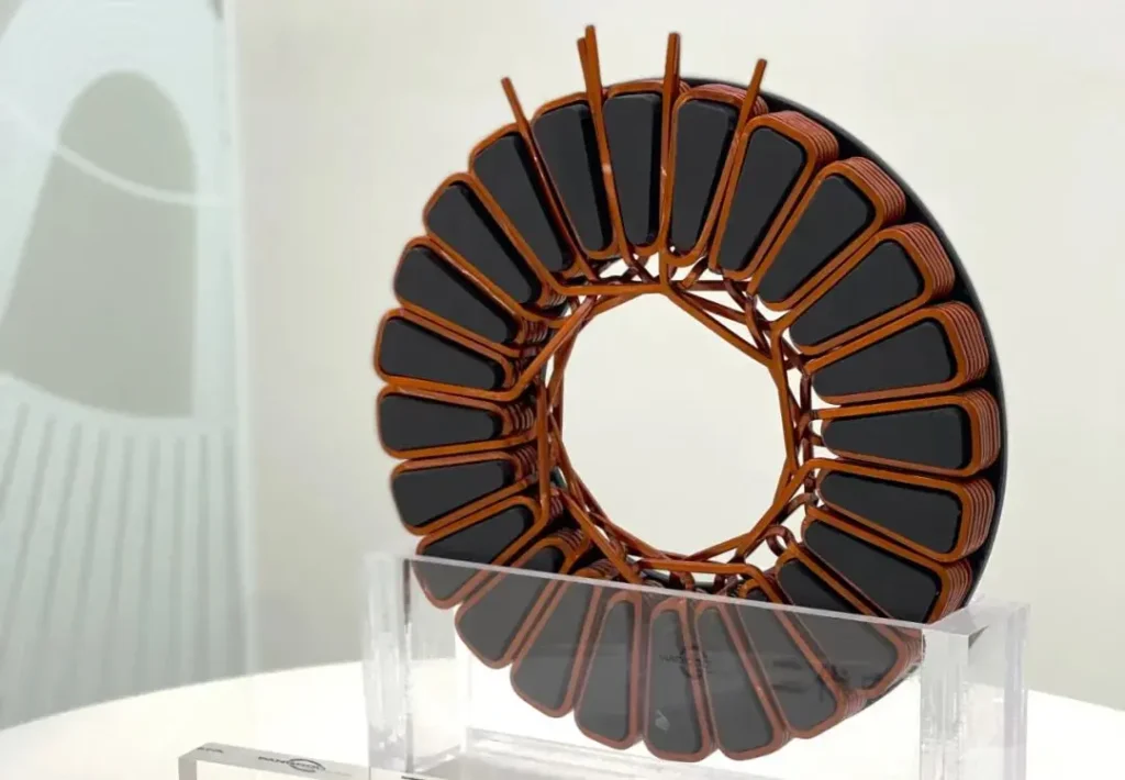
Axial Flux Motor for Electric Vehicles: A Comprehensive Overview Brogen axial flux motor A new type of electric motor — the axial flux motor — is gaining increasing attention in the electric vehicle industry. For years, axial flux motors have been used in stationary applications such as elevators and agriculture machinery. However, over the past decade, many developers have been working to refine this technology, making it suitable for a wide range of applications, including electric motorcycles, airport shuttles, cargo trucks, electric vehicles, and even aircraft. The Emergence of Axial Flux Motor: The World’s First Generator Faraday motor In 1831, British physicist Michael Faraday harnessed the phenomenon of electromagnetic induction to invent the world’s first true electric generator, known as the Faraday disk generator. This invention can be seen as the prototype of the axial flux motor. The Faraday disk generator consisted of a disk, brushes, and a horseshoe magnet. Faraday placed a rotatable metal disk within the magnetic field of the magnet and used a galvanometer to measure the current between the edge of the disk and its center. The experiment demonstrated that when the disk rotated, the galvanometer deflected, confirming the presence of current in the circuit—thus achieving the conversion of mechanical energy into electrical energy. Faraday generator reconstruction However, due to limitations in materials, structure, and manufacturing techniques, as well as the late emergence of demand for mobile electric equipment such as electric vehicles, axial flux motors remained largely undeveloped for nearly 200 years. The primary challenges included difficulties in electromagnetic calculations, material selection, complex manufacturing processes, and the intricate coupling between materials, structure, and techniques—all of which exponentially increased the difficulty of industrializing this technology. Axial Flux Motor in the Era of Automotive Electrification While radial flux motors have driven the automotive industry into the electrical age, axial flux motors outperform them in several key areas. Not only are they lighter and more compact, but they also deliver greater torque and power. This groundbreaking technology enables a smaller and lighter motor to generate more powerful force, opening up a world of new possibilities for automotive designers. The most significant difference between axial flux motors and traditional radial flux motors lies in the direction of the magnetic flux. In axial flux motors, the magnetic flux is parallel to the motor’s axis, unlike in radial flux motors where it is perpendicular to the axis. This fundamental difference leads to a considerable change in the stator’s structure. Below are some structural diagrams to help illustrate this concept. A New Benchmark in Performance Traditional radial flux motors, which use permanent magnets or induction in the electric field, are currently being widely developed to optimize weight and cost. However, there is a limit to how much can be improved within this design. Therefore, switching to a completely different type of motor, like the axial flux motor, could be a promising alternative. The torque in a radial flux motor is proportional to the square of the rotor radius, while in an axial flux motor, torque is proportional to the cube of the rotor radius. This means axial flux motors can produce significantly higher torque. For instance, with the same output power, an axial flux motor is 50% smaller and 50% lighter than a radial flux motor. A prime example is the axial flux motor in the Mercedes Vision One-Eleven all-electric concept car, which weighs only one-third of a conventional motor with the same power output. Mercedes Vision One-Eleven Design and Efficiency Advantages The size and weight advantages of axial flux motors not only greatly reduce the use of materials like copper, iron, and permanent magnets in production, but also allow for more flexible placement in tighter spaces, such as the recesses of car wheels. this reduces the need for components like transmissions and drive shafts, minimizing kinetic energy loss and improving drive efficiency. The direct torque compensation further enhances performance.  Streamlined Structure and Enhanced System Benefits Due to their compact and lightweight design, axial flux motors require fewer structural elements for installation, saving even more weight. Additionally, their rotational speed does not reach the high levels seen in traditional radial flux motors, eliminating the need for reduction gears. This further reduces the overall system weight, benefiting other subsystems like braking and cooling. Overall, this can lead to a 5-10% improvement in both efficiency and range. Technical Challenges for The Axial Flux Motor Despite the technical advantages of axial flux motors and the significant progress made over the years, the industry has now grasped the working principles of these motors and has largely overcome key challenges in configuration and structural design, electromagnetic performance, thermal performance, and the development of calibration and control strategies. However, the large-scale application remains a challenge due to several design and production hurdles that must be addressed:  1. Immature Manufacturing Equipment The industry’s understanding of axial flux motor manufacturing methods is still limited due to a lack of research and experience. Manufacturing equipment is not readily available, and the supply chain is underdeveloped. 2. High Manufacturing Precision Requirements Axial flux motors must maintain a uniform air gap between the rotor and stator, as the magnetic force is much stronger than in radial flux motors. Adjusting the air gap during the motor manufacturing process is challenging, making it crucial to precisely control the tolerance of key components. 3. Thermal management and Design Complexity Axial flux motors feature a sandwich structure, making it difficult to dissipate heat from the central stator in dual-rotor designs or the central rotor in dual-designs. Additionally, due to their high power density, axial flux motors have a small heat capacity, leading to overheating issues. Innovative cooling methods, such as immersion oil cooling, oil-water hybrid cooling, liquid nitrogen cooling, and phase-change material cooling, are needed, along with the design of  complex cooling and sealing structures. 4. High Costs Due to Complex Materials and Processes For radial flux motors, the costs of magnets, silicon steel, copper, and structural components, as well as the manufacturing processes for mass

Scroll to Top