DC-DC Converter in EVs: Role, Architecture, and Opearting Principles
1. The Role of a DC-DC Converter
In simple terms, a DC-DC converter in an electric vehicle (EV) is a step-down voltage converter. Its primary function is to convert the high-voltage DC power from the traction battery into the low-voltage DC power required by the vehicle’s auxiliary electrical system.
- Conventional internal combustion engine (ICE) vehicles: Powered by an alternator and a 12V lead-acid battery, which supply electricity to components such as headlights, infotainment systems, the ECU, power windows, door locks, and wipers.
- Electric vehicles: Since there is no engine, there is no alternator. Instead, EVs rely on a high-voltage traction battery (typically 200V-800V) for propulsion. However, most onboard systems – such as the instrument cluster, lighting, infotainment, controllers, and window motors – still operate on a traditional 12V low-voltage system. Without a conversion path, energy cannot flow between the high-voltage and low-voltage domains.
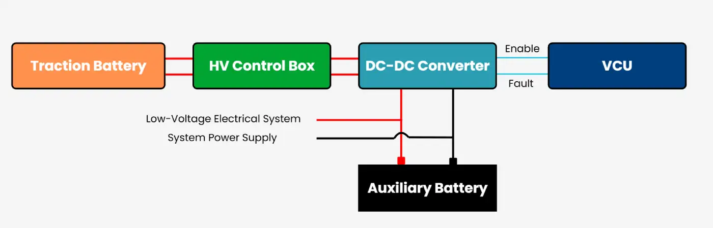
The DC-DC converter bridges this gap. It replaces the alternator in ICE vehicles and acts as the core low-voltage power supply in EVs.
2. Circuit Composition of a DC-DC Converter
Most EVs use isolated LLC resonant DC-DC converters, either unidirectional or bidirectional. While sophisticated in design, their operating principle is similar to that of a common switch-mode power supply. A typical DC-DC converter consists of the following components:
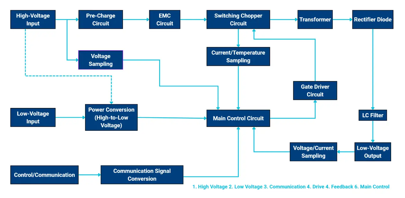
2.1 Main Power Circuit
- Input EMI filer: Smooths the high-voltage DC from the traction battery, reducing voltage ripple and electromagnetic interference.
- Power switching stage: Typically a half-bridge or full-bridge structure. Controlled by high-frequency switches (MOSFETs/IGBTs), the DC input is inverted into a high-frequency AC square-wave signal. This is the core of energy conversion.
- High-frequency transformer:
- Electrical isolation: Provides galvanic isolation between high-voltage and low-voltage sides for safety and noise immunity.
- Voltage transformation: Achieves step-down conversion according to the winding ratio.
- Output rectifier: Converts the transformer’s secondary high-frequency AC into DC. Typically implemented with diodes or synchronous rectification MOSFETs.
- Output filter: A combination of inductors L and capacitors C smooths the rectified DC to provide a stable 12V output.
2.2 Control and Drive Circuit
- Main control unit: The “brain” of the DC-DC converter. It continuously monitors voltage and current, compares them with reference values, and generates PWM signals to adjust the duty cycle of the switching devices for precise voltage regulation.
- Driver circuit: Amplifies the PWM signals from the control unit to ensure the power switches operate rapidly and efficiently.
- Sampling and protection circuit: Continuously monitors input voltage, output voltage, output current, and temperature. In case of over-voltage, under-voltage, over-current, over-temperature, or short-circuit conditions, the controller immediately shuts down PWM input to protect both the converter and the low-voltage system.
3. Operating Principle of a DC-DC Converter
The working process can be summarized in four stages: DC → High-Frequency AC → Transformation → DC.
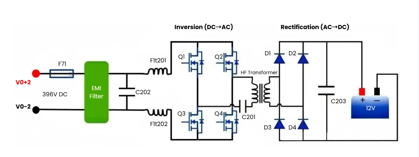
- Inversion (DC-AC): The control unit generates four PWM signals to alternately drive the switches in the full-bridge circuit (Q1-Q4). This converts the high-voltage DC (e.g., 400V) into a high-frequency AC square wave, typically in the kHz range.
- Transformation & Isolation: The AC signal passes through the LLC resonant tank, enabling zero-voltage switching (ZVS) of MOSFETs, which minimizes switching losses and improves efficiency. The high-frequency transformer then steps down the voltage and provides galvanic isolation.
- Rectification (AC-DC): The transformer’s secondary AC output is rectified by the output stage, often using synchronous rectification with MOSFETs to reduce conduction losses compared to diodes.
- Filtering & Output: The rectified pulsating DC passes through an LC filter to produce a stable 12V DC supply for onboard low-voltage devices.
- Closed-Loop Feedback Control: The control chip continuously monitors the output voltage via sampling resistors. If the load increases (e.g., headlights and AC operating simultaneously) and the voltage drops, the controller increases the PWM duty cycle to deliver more energy to the low-voltage side, restoring the output to 12V. If the load decreases, the duty cycle is reduced. This negative feedback loop ensures that the DC-DC converter maintains an extremely stable 12V supply regardless of load variations.
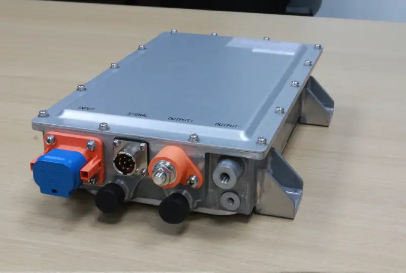
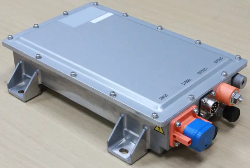
Our DC-DC Converter Solutions
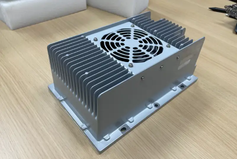
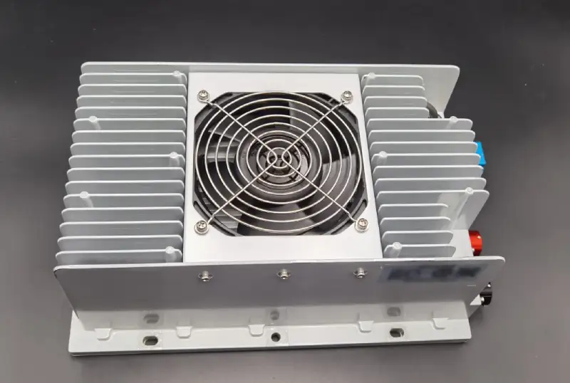
At Brogen, we provide a full range of DC-DC converter solutions for electric vehicles, covering power outputs from 0.6 kW to 6 kW, with options for natural, air, or water cooling. Our portfolio also includes OBC & DC-DC combo units, as well as 3-in-1 CDU combo units that integrate the OBC, DC-DC, and PDU into a single compact system.
- Learn more here: https://brogenevsolution.com/obc-dcdc-pdu/
- Looking for an EV solution for your project? Reach out to us at contact@brogenevsolution.com
Contact Us
Get in touch with us by sending us an email, using the Whatsapp number below, or filling in the form below. We usually reply within 2 business days.
Email: contact@brogenevsolution.com
Respond within 1 business day
Whatsapp: +8619352173376
Business hours: 9 am to 6 pm, GMT+8, Mon. to Fri.
LinkedIn channel
Follow us for regular updates >
YouTube channel
Ev systems introduction & industry insights >