Designing Better BEV Traction Battery Systems
Brief Introduction
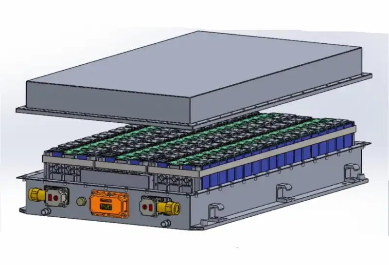
Designing a suitable traction battery system for Battery Electric Vehicles (BEVs) is crucial for ensuring optimal performance, safety, and longevity of the vehicle. As BEVs become increasingly popular due to their environmental benefits and efficiency, the demand for advanced battery systems continues to grow. A well-designed traction battery system not only meets the power and range requirements of the vehicle but also addresses critical factors such as safety, cost, and environmental impact. In this blog, we will explore the key aspects of designing a traction battery system, including safety and performance requirements, issues to be addressed, design processes, and the information needed about the vehicle to achieve a perfect design, as well as a detailed case study of designing a battery system.
Purpose of the EV Traction Battery System Design
To provide a traction battery system with optimal performance based on the design requirements of the entire vehicle.
- Safety performance requirements
- Electrical performance requirements
- Battery selection and system configuration
Issues to be Addressed
- Design structure and process within allowable size and weight to meet the vehicle’s power requirements
- Find simple and feasible processes
- Reduce costs
- Improve technical performance where conditions permit
- Address and resolve environmental pollution issues
EV Traction Battery Design Process
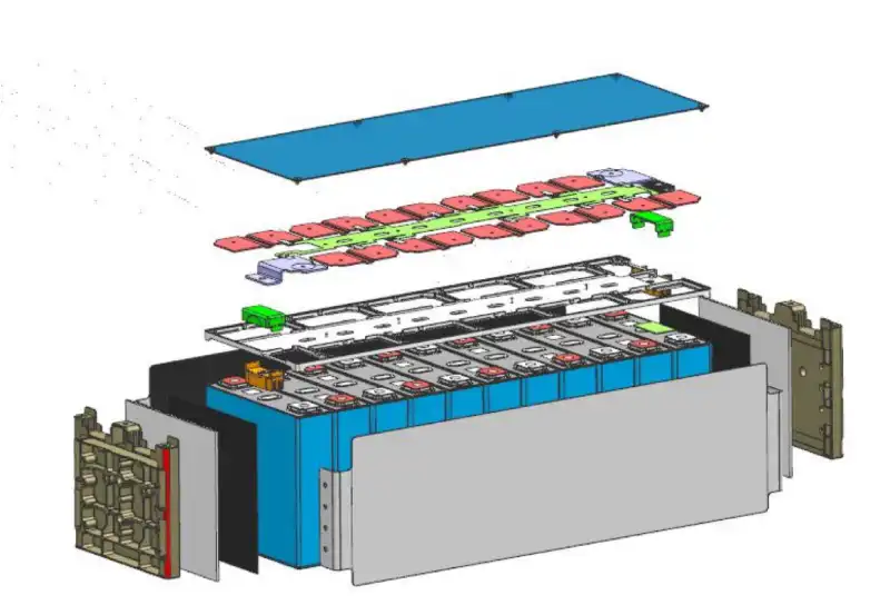
- Understand vehicle requirements
- Design system power
- Design system capacity
- Thermal design
- System integration
- Simulation and validation
Parameters to Determine and Issues to Address
1. Electrical Characteristics
- Nominal voltage and operating voltage range;
- Nominal capacity and available capacity range;
- Regular discharge current of the traction battery system;
- Charging requirements of the traction battery system.
2. Power Characteristics
- Maximum output power and duration of the traction battery system;
- Maximum regenerative power and duration of the battery system.
3. Environmental Characteristics
- Operating temperature range of the traction battery system;
- Charging temperature range;
- Storage temperature range.
4. Physical Characteristics
- Structural and dimensions of the traction battery system;
- Quality of the traction battery system;
- Other mechanical performance and protection requirements.
5. BMS Requirements
6. Vehicle Interface Requirements
- Physical interfaces: battery installation, fixing methods, space orientation of cooling medium, and related pipelines;
- Electrical interfaces: vehicle harness definition and technical specifications, connector model, and pin definitions;
- Communication interfaces: communication with the vehicle, internal communication of the BMS, communication with the charger.
Information Needed About the Vehicle
The more detailed the understanding of the vehicle, the more perfect the traction battery system design will be. Not only the motor and vehicle control strategies but also the vehicle’s mass, dimensions, space, and operating conditions must be thoroughly understood:
- Vehicle parameters
- Vehicle motor parameters
- Required driving range of the vehicle
- Regenerative power
- Installation space dimensions of the traction battery system and installation and fixing requirements
- Quality requirements of the traction battery system
- Charging methods and interfaces
- Vehicle operating conditions
- Operating environment temperature range
- Charging environment temperature range
- Power requirements of auxiliary systems
- Characteristic parameters of the auxiliary battery
Traction Battery System Design Steps
- Determine vehicle design requirements
- Determine motor requirements
- Determine power requirements of the traction battery system
- Determine the voltage range of the traction battery system
- Determine the type of batteries required for the traction battery system
- Determine the SOC application range of the traction battery system
- Determine the effective and actual capacity range of the traction battery system
- Determine the combined structure of the traction battery system
- Determine the BMS requirements of the traction battery system
- Determine the interfaces of the traction battery system
- Determine other methods such as cooling methods, gas sources, and charging methods
- Simulation and validation
- Design optimization
Case Study
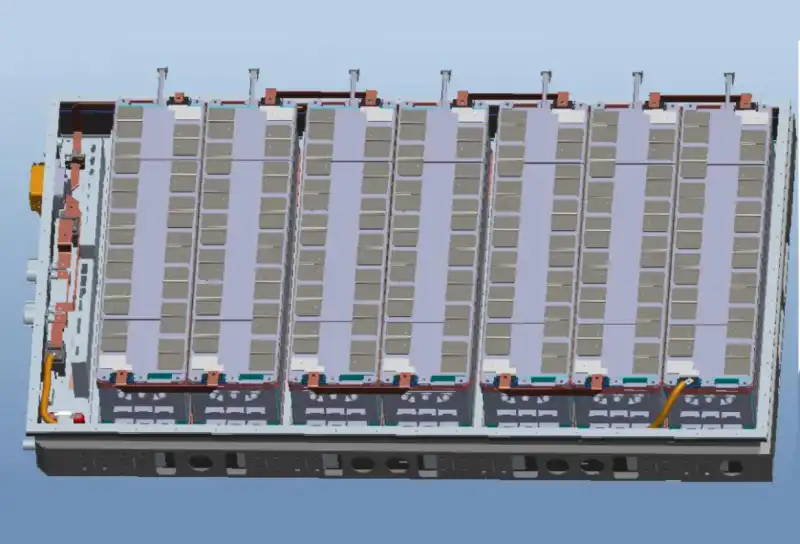
With the following parameters for a BEV, explore how to design a suitable traction battery system to ensure optimal performance, safety, and efficiency.
- Curb weight: 12600 kg
- Gross weight: 17150 kg
- Wheelbase: 5980 mm
- Frontal area: 7.95 m²
- Transmission system efficiency: 0.92
- Aerodynamic drag coefficient: 0.7
- Rolling resistance coefficient: 0.0076+0.000056Vv
- Required acceleration time: 13 s
- Required driving range: 200 km (average speed at 40 km/h)
- Power consumption for electronic accessories and air conditioning: 8 kW
Step 1: Determine the vehicle's power requirements
The power balance relationship of an automobile should satisfy:

The vehicle power requirement (Pv1) corresponding to the maximum vehicle speed is:

The vehicle power requirement (Pv2) corresponding to the maximum climbing grade αm is:

The vehicle’s power requirement Pv3 for accelerating from a standstill to a specified acceleration time T is given by the following formula. The required power during full-throttle acceleration is Pv3.

The power requirements of the vehicle under different conditions – maximum speed, maximum climbing gradient, and full acceleration – are as follows: 98.7 kW, 91.8 kW, and 65 kW, respectively.
Step 2: Determine the system voltage range
Based on the selected motor for the vehicle, determine the nominal voltage and voltage application range of the traction battery system. Standards require that the motor and controller safely handle the maximum current within 120% to 75% of the rated voltage. Additionally, the DC bus voltage should not fall below 80% of the motor’s rated voltage. For instance, if the vehicle uses a 384 V motor, the battery system should operate within a voltage range of 300 to 460 V. In this case, a lithium iron phosphate (LiFePO4) battery system with 120 cells connected in series is selected.
Step 3: Determine the maximum output power / current of the system
- Power supply system power requirements: the motor power is 110 kW. Assuming the motor efficiency and controller efficiency are 0.9 and 0.95, respectively, and the power for electronic accessories and air conditioning is 8 kW, the minimum power required by the power supply system is calculated as follows: 110/(0.9×0.95)+8=137 kW
- Maximum output current: the system’s nominal voltage is 384 V. For high-power output, it’s calculated at 10% below the nominal voltage: Idmax=Pmax/V=137000/(384×0.9)=396 A
- Duration: the duration should meet the requirements of the entire vehicle, taking into account the SOC requirements (the maximum power demand at 30% SOC).
- Design redundancy: ensuring a 30% design redundancy is necessary.
Step 4: Regenerative power and vehicle control strategy
- The regenerative power is related to the vehicle’s control strategy. The regenerative power is less than the motor’s maximum power. For a 110 kW motor, the maximum generating power is approximately 70 kW, so the regenerative current is Icmax=70000/432=162 A.
- Regenerative duration: the duration is determined based on vehicle operating conditions (e.g., 10 seconds).
- SOC range: the SOC range is determined according to the battery characteristics, such as at 70% SOC.
- Vehicle braking regenerative strategy: the proportion of mechanical braking and motor braking energy recovery. Motor regenerative power is usually smaller, with actual power being less than the maximum generating power. Assuming 50% of the maximum power is recovered, the regenerative power is 55 kW, and the current is approximately 100 A.
Step 5: Determine the SOC application range of the battery system
- To better protect the EV battery system, it’s generally not recommended to fully charge or completely discharge the battery in practical applications, as this can easily damage the battery. It is typically advised to charge the battery to 95% to 100% and leave 5% to 10% capacity remaining when discharging. This helps to better protect the weaker battery cells within the system.
- The recommended application range is 10% – 90% SOC.
Step 6: Determine the capacity of the battery system
Calculation based on average driving speed and mileage: the average driving speed is 40 km/h, and the average output power is 25 kW. The motor’s rated voltage is 384 V, and the required driving range is not less than 200 km. Then the capacity of the battery system is 25000×200/(40×384)=325 Ah
- Calculation based on energy consumption per kilometer: the vehicle’s energy consumption per kilometer is approximately 0.63 kWh. The required driving range is 200 km. The system’s nominal voltage is 384 V. Then the battery system capacity is 200×630/384=328 Ah. So the battery pack should provide the actual capacity of 328 Ah. The capacity of the battery system should be 328/0.8=410 Ah. (0.8 is the SOC application range of the vehicle).
- Calculation based on the vehicle’s parameters: the average driving speed of the vehicle is 40 km/h, and the driving range is 200 km. So the required continuous driving duration is 5 hours. The driving power requirement is Pv1=25 kW. So the required energy should be W=25×5=125 kWh. And the capacity of the battery system should be 125×1000/(384×0.8)=407 Ah.
- Redundancy design: when designing the capacity, redundancy needs to be considered. Generally, the design redundancy is 30% (which can be determined according to the actual situation). This design can use a 500 Ah battery system.
Step 7: Battery pack heat dissipation design
- Calculate the heat generated and the possible temperature rise during normal vehicle operation according to the normal working conditions of the vehicle. Calculate the heat generation during the charging process based on the charging requirements.
- Determine the cooling method to be adopted based on the calculation results.
- Calculate based on the charge and discharge curve.
- Calculate based on DC internal resistance.
Step 8: BMS functions design
- The Battery Management System (BMS) should be designed according to the requirements of the selected battery type, vehicle control requirements, and communication protocol.
- Determine equalization current based on battery characteristics: the equalization current is determined based on the characteristics of the selected battery. In this case, a 500 Ah lithium iron phosphate (LFP) battery system is used. Assuming a monthly self-discharge rate of approximately 5% (with a monthly capacity difference of up to 5% between batteries), and a daily charging equalization time of around 2 hours, the equalization current should be 500×5%/(30×2)=0.417 A to eliminate the capacity differences caused by self-discharge.
Customize Your EV Traction Battery System With Brogen
At Brogen, we specialize in customizing EV traction battery systems to help manufacturers save time and reduce costs. Our high energy, high-safety battery systems are designed for a wide range of electric vehicles, including BEVs, HEVS, and FCEVs. Additionally, we provide fast-charging battery packs for heavy equipment. Discover more about our innovative EV battery solutions here.
Contact Us
Get in touch with us by sending us an email, using the Whatsapp number below, or filling in the form below. We usually reply within 2 business days.
Email: contact@brogenevsolution.com
Respond within 1 business day
Whatsapp: +8619352173376
Business hours: 9 am to 6 pm, GMT+8, Mon. to Fri.
LinkedIn channel
Follow us for regular updates >
YouTube channel
Ev systems introduction & industry insights >
