In-Depth Overview of Battery Thermal Management Systems for Electric Semi Trucks
As electric semi trucks gain traction in global logistics, maintaining battery performance and safety under varied environmental conditions is critical. This is where the Battery Thermal Management System (BTMS) comes into play.
1. Introduction of BTMS for Electric Semi Trucks
The Battery Thermal Management System (BTMS) in electric semi trucks is a closed-loop liquid cooling system composed of coolant circuits and thermal conductive media. By leveraging sensors and a control unit, the system actively regulates coolant temperature to keep the traction battery pack operating within an optimal thermal range. This ensures peak battery performance, extends service life, and enhances overall vehicle safety.
1.1 Key Functions of the BTMS
- Cooling: When battery cell temperatures rise excessively, the system activates cooling to prevent thermal runaway and potential safety incidents.
- Preheating: In low-temperature environments, the system preheats the battery cells to ensure safe and efficient charging/discharging operations.
- Temperature Equalization: It reduces internal temperature differences among cells, minimizing localized overheating and maintaining uniform battery performance.
1.2 Structure and Operating Principle
The BTMS consists of the following major components:
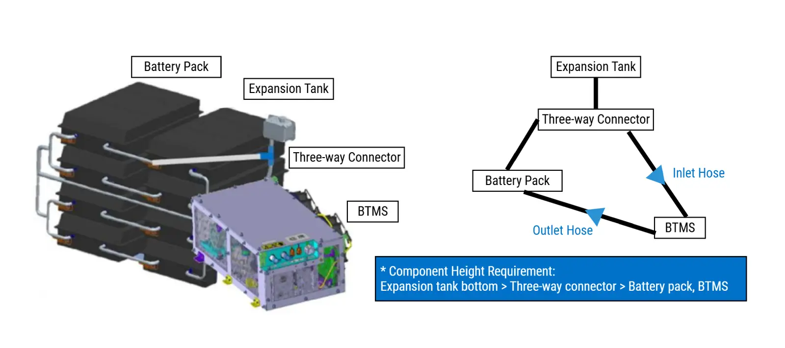
- Liquid Cooling Unit: Provides pressurized, temperature-regulated coolant to the system.
- Expansion Tank: Manages fluid storage, replenishment, and thermal expansion.
- Coolant Pipes: Serve as channels for the antifreeze coolant and connect with the battery’s internal cooling plates to form a sealed loop.
- Antifreeze Coolant: Acts as the heat transfer medium.
Two common layout configurations exist for the cooling unit – top-mounted or bottom-mounted on the battery pack. The expansion tank is located on the top of the battery pack.
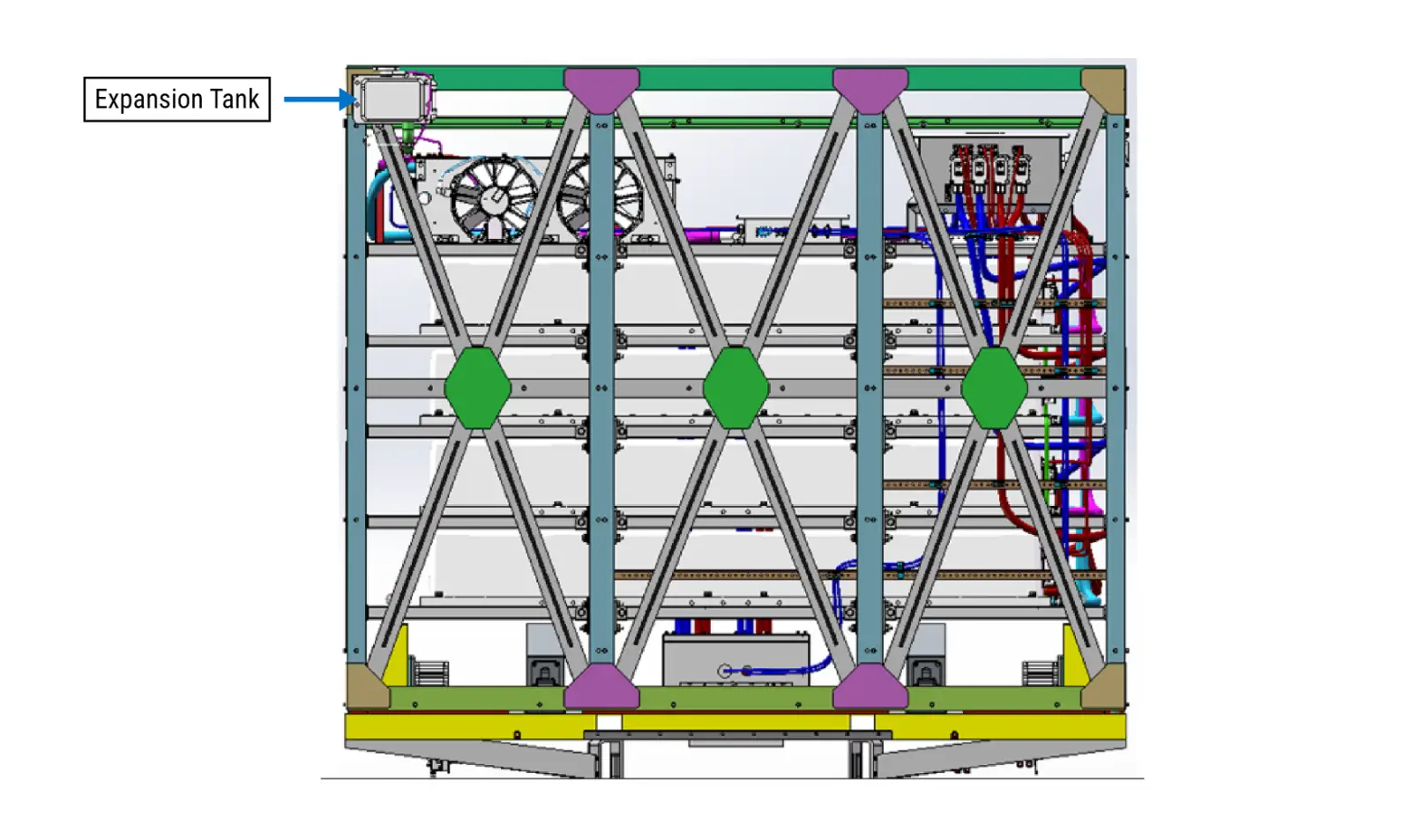
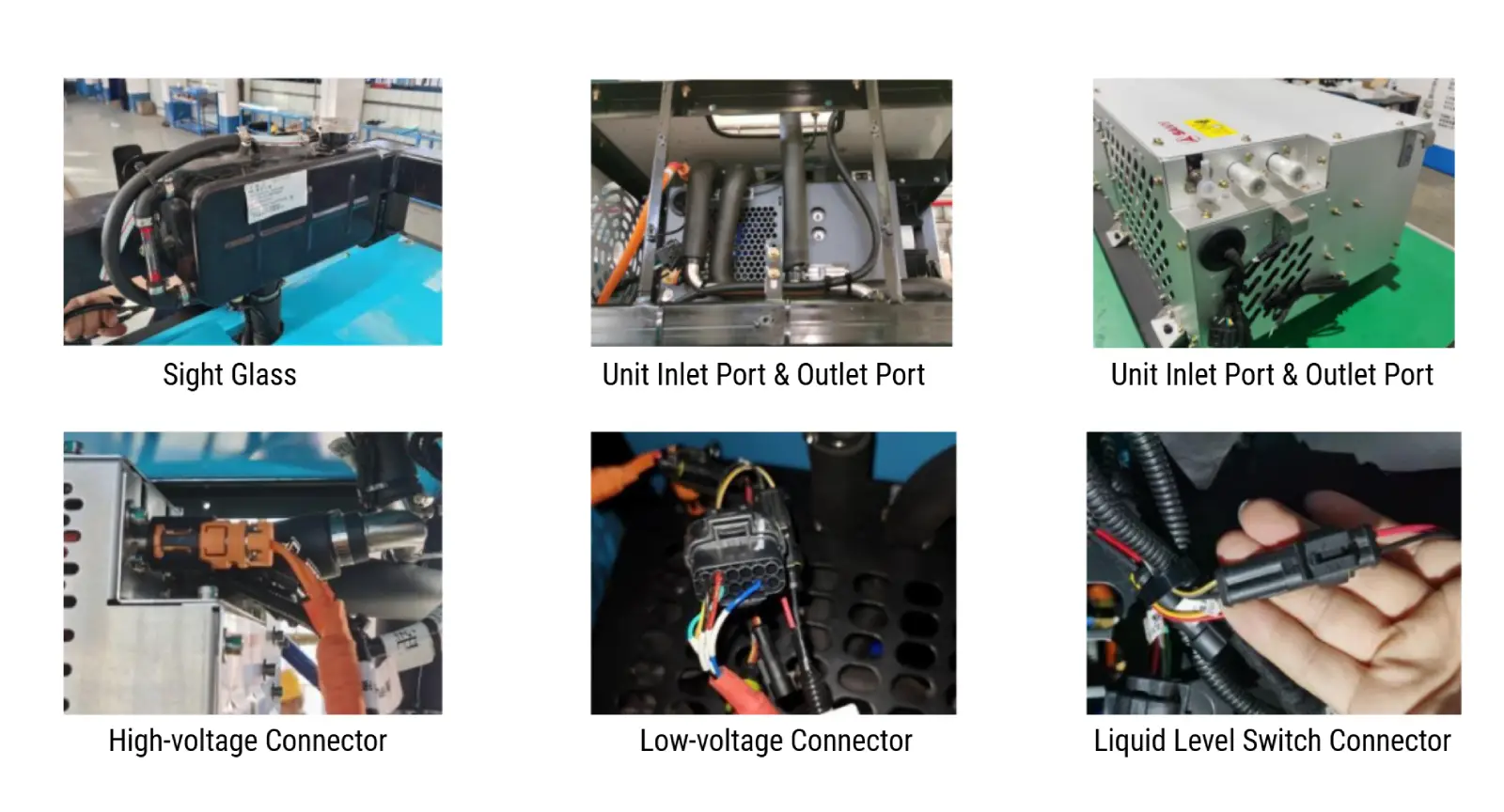
System interfaces include 1 observation window, 2 coolant ports, and 3 electrical connectors.
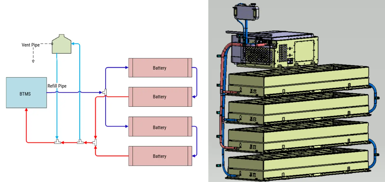
1.3 System Schematic and Configurations (Examples)
- 282 kWh Battery System (Charging or Swappable Version): Consists of four H-type modules arranged in a 2-parallel x 2-series configuration.
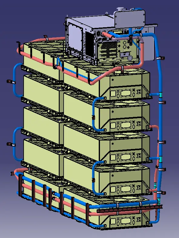
- 350 kWh Battery System (Charging or Swappable Version): Includes ten C-type modules arranged in a 5-parallel x 2-series configuration.
2. Liquid Cooling Unit: Three Thermal Circuits
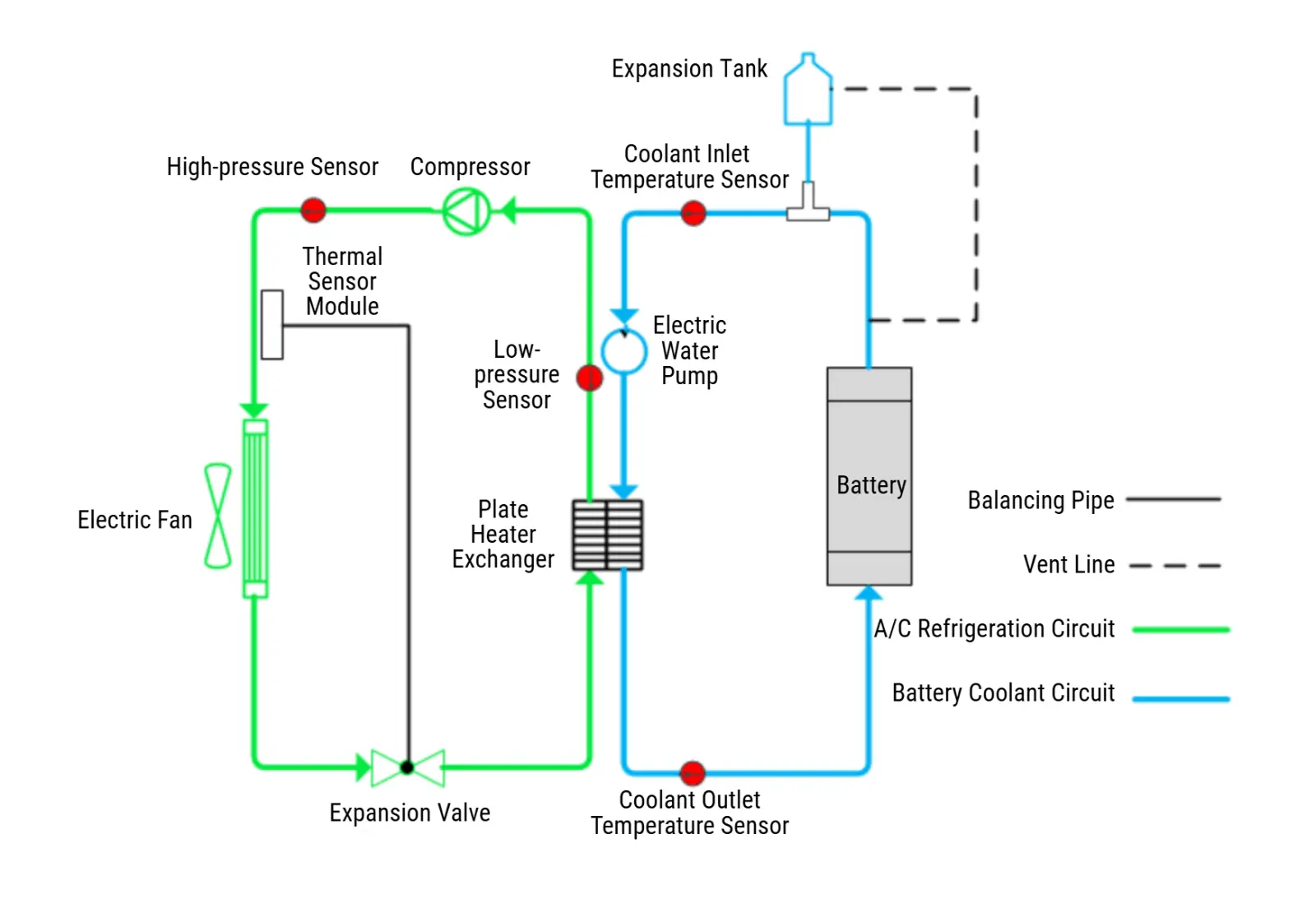
The battery thermal management relies on three interlinked circuits:
- Liquid Cooling Circuit: Electric water pump, plate heat exchanger, battery cooling channels
- Refrigerant Circuit: Compressor, condenser, expansion valve, plate heat exchanger
- Air Circuit: Electric fan, condenser
There are two heat exchange interfaces:
- Plate Heat Exchanger: Enables heat transfer between the refrigerant loop and the liquid cooling loop.
- Condenser: Transfers heat between the refrigerant loop and the air circuit.
Key Components and Functions
- Integrated Controller: This unit combines three control modules – PLC, DC-DC, and DC-AC – in one compact system. It collects data from high-pressure and low-pressure sensors, as well as inlet and outlet temperature sensors. The controller receives operational commands and target coolant temperatures from the BMS, enabling precise control over the operation of the electric water pump, compressor speed, and electric fan speed.
- Compressor: A core component of the refrigerant circuit, the compressor is responsible for absorbing, compressing, and discharging the refrigerant to maintain circulation. The cooling capacity of the liquid cooling loop depends on the proper functioning of the compressor.
- Electric Water Pump: It drives the circulation of antifreeze within the liquid cooling loop. It plays a vital role in transferring heat away from the battery cells through the liquid-cooled plates. Without proper pump operation, battery cooling cannot be achieved effectively.
- Electric Fan: Mounted on the exterior side of the condenser, this suction-type fan delivers continuous airflow across the condenser surface, dissipating the heat absorbed by the refrigerant. If the fan fails to operate correctly, the system may experience pressure faults due to insufficient heat dissipation.
- Condenser: The condenser transforms high-temperature, high-pressure gaseous refrigerant into a high-pressure liquid state. If the condenser becomes clogged or dirty, airflow is reduced, leading to decreased heat transfer efficiency and diminished cooling capacity. This results in minimal temperature difference across the coolant circuit and continuous temperature rise in battery cells, which may trigger system pressure alarms. Regular cleaning and maintenance of the condenser are essential for safe operation in electric vehicles.
- Plate Heat Exchanger: This component facilitates thermal exchange between the low-temperature refrigerant and the high-temperature antifreeze. After passing through the exchanger, the antifreeze temperature typically drops by 2°C to 5°C under normal operating conditions.
- Expansion Valve With Thermal Sensing Bulb: This valve converts the refrigerant from a medium-temperature, high-pressure liquid into a low-temperature, low-pressure liquid. The thermal sensing bulb detects temperature inside the cooling pipe and adjusts the valve’s operating accordingly to regulate refrigerant flow. Due to its high sensitivity to temperature fluctuations, the expansion valve and thermal bulb are insulated with protective layers.
- Sensors: High-pressure and low-pressure sensors monitor pressure levels within the refrigerant circuit. Inlet and outlet temperature sensors measure coolant temperatures at the water inlet and outlet of the liquid cooling unit. These signals are sent to the PLC controller, which uses the data to dynamically manage the operation and speed of the compressor, water pump, and fan, ensuring stable and efficient thermal regulation.
Our Battery Thermal Management Solutions for Electric Semi Trucks
At Brogen, we provide tailored EV battery systems along with BTMS solutions. For electric semi-trucks and other heavy-duty vehicles, we offer standard 272 kWh and 350 kWh battery systems, paired with BTMS units ranging from 5 kW to 10 kW.
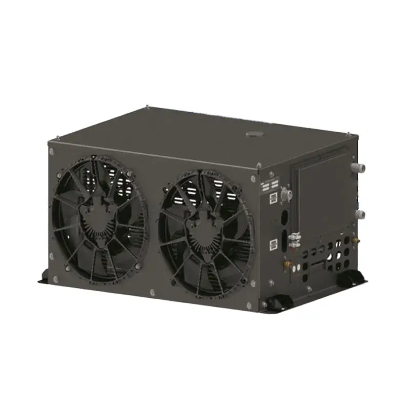
The thermal units feature a lightweight aluminum alloy frame and can be optionally equipped with PTC liquid heaters. They support multiple operation modes, including standby, cooling, heating, and self-circulation. Communication is based on the CAN bus protocol, with built-in self-diagnosis, real-time status monitoring, and fault reporting capabilities.
In addition, we offer integrated thermal management solutions tailored to customer requirements. These systems share components, such as the compressor and condenser, between the air-conditioning circuit and the battery cooling system. The architecture includes dual evaporator circuits: one for cabin climate control and the other for battery temperature regulation. The battery cooling loop uses a secondary liquid-cooling heat exchange approach to ensure efficient and stable thermal performance.
Technical Parameters
| Model | OETLE205 | OETLE207 | OETLE208 | OEEFDR-01 | OEEFDR-02 | OEEFDR-03 | OEEFDR-04 |
| Cooling capacity | 5 kW | 7 kW | 8 kW | 3 kW | 5 kW | 8 kW | 10 kW |
| Low voltage power consumption | 500 W | 700 W | 700 W | 450 W | 800 W | 800 W | 1000 W |
| High voltage input | DC 400-750 V | DC 400-750 V | DC 400-750 V | DC 400-750 V | DC 400-750 V | DC 400-750 V | DC 400-750 V |
| Low voltage input | DC 24 V | DC 24 V | DC 24 V | DC 24 V | DC 24 V | DC 24 V | DC 24 V |
| Low voltage power supply | Vehicle provided | DC conversion | Vehicle provided | DC-DC (standard configuration) / Vehicle provided | DC-DC (standard configuration) / Vehicle provided | DC-DC (standard configuration) / Vehicle provided | DC-DC (standard configuration) / Vehicle provided |
| Control power | DC 24 V ON/OFF signal | DC 24 V ON/OFF signal | DC 24 V ON/OFF signal | DC 24 V ON/OFF signal | DC 24 V ON/OFF signal | DC 24 V ON/OFF signal | DC 24 V ON/OFF signal |
| Size | L643*W599*H3863 mm | L835*W560*H310 mm | L669*W621*H461 mm | L685*W600*H280 mm | L685*W600*H280 mm | L818*W600*H280 mm | L1005*W557*H280 mm |
| Refrigerant | R134a | R410a | R134a | R134a | R134a | R407C/ R134a | R407C |
| Water pump | Q=1200L/h, H>10m | Q=2400L/h, H>13m | Q=2800L/h, H>16m | 100 W | 180 W | 240 W | 240 W |
| Pipe diameter | 25 mm | 25 mm | 25 mm | 25 mm | 25 mm | 25 mm | 25 mm |
| Expansion tank | No | No | No | Can be integrated | |||
| PTC heater | No | No | No | Reserve 5 kW / 10 kW / 14 kW / 24 kW for selection | |||
- Discover our BTMS Solutions here: https://brogenevsolution.com/battery-thermal-management-system-btms/
About Brogen
At Brogen, we provide advanced EV solutions for global commercial vehicle manufacturers, enabling them to streamline research and development while capitalizing on cutting-edge technology. Our offerings ensure superior efficiency, extended range, and seamless system integration with proven reliability—empowering our partners to lead in the rapidly evolving green mobility landscape.
Currently, our EV solutions for battery electric heavy trucks have been adopted by vehicle manufacturers in countries and regions such as Canada, Türkiye, Brazil, the Philippines, Indonesia, the Middle East, and more.
- Discover our HCV electrification solution here: https://brogenevsolution.com/heavy-duty-vehicle-electrification-solutions/
- Looking for an EV solution for your project? Reach out to us at contact@brogenevsolution.com
Contact Us
Get in touch with us by sending us an email, using the Whatsapp number below, or filling in the form below. We usually reply within 2 business days.
Email: contact@brogenevsolution.com
Respond within 1 business day
Whatsapp: +8619352173376
Business hours: 9 am to 6 pm, GMT+8, Mon. to Fri.
LinkedIn channel
Follow us for regular updates >
YouTube channel
Ev systems introduction & industry insights >