Vehicle Control Unit (VCU) Explained: A Deep Dive into Software Architecture
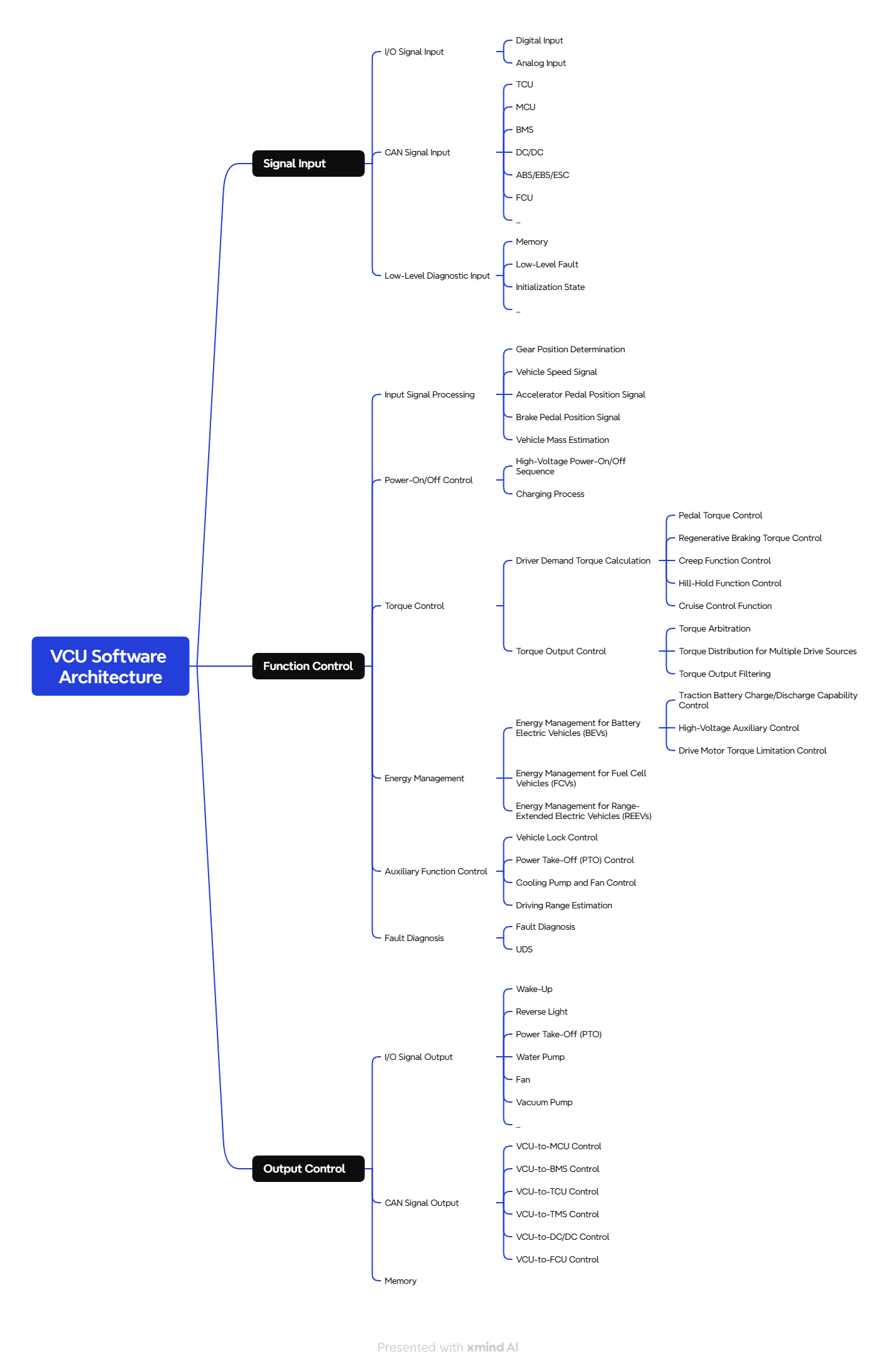
The Vehicle Control Unit (VCU) is often referred to as the “brain” of the vehicle. It plays a pivotal role in managing and coordinating various systems to ensure efficient, safe, and intelligent vehicle operation. At the core of its operation is a well-structured software architecture, typically divided into three key parts: Signal Input, Function Control, and Signal Output.
1. Signal Input – The “Senses” of the Vehicle Control Unit (VCU)
The signal input section enables the VCU to perceive the vehicle’s real-time status, much like how human senses gather information from the environment. The VCU collects data from three primary channels: hardwired inputs, the CAN bus (Controller Area Network), and low-level diagnostic signals.
- Hardwired Inputs: These are like the vehicle’s nerve endings, directly connected to key components. Through these inputs, the VCU gathers critical information such as accelerator position, brake pedal status, ignition key state, and more. This data reflects the driver’s direct commands and helps the VCU respond accordingly.
- CAN Bus Inputs: Acting as the vehicle’s internal communication highway, the CAN bus connects essential systems such as the battery management system (BMS), motor control unit (MCU), and transmission control unit (TCU). The VCU monitors these systems in real time, allowing precise and coordinated vehicle control.
- Low-Level Diagnostics: This includes internal controller states, E-flash storage signals, and I/O diagnostics. Think of it as the vehicle’s health report, providing deeper insights to support system reliability and performance monitoring.
2. Function Control – The “Brain” of the Vehicle Control Unit (VCU)
This is the core processing layer of the VCU. Based on the inputs received, the VCU makes intelligent decisions to manage vehicle behavior. While features may vary between manufacturers, most VCUs include the following key control functions:
- Input Signal Processing: Acts as a centralized filter and organizer. It processes signals such as speed, acceleration, braking, gear logic, and vehicle weight. By unifying data at this layer, the VCU improves efficiency and reduces redundant signal processing across different functional modules.
- Power Management (Power On/Off Control): The VCU coordinates the high-voltage system to manage key processes, including pre-charging, enabling power output, and entering sleep modes. It ensures components are powered on or off in a safe and orderly manner. Additional features like smart battery charging and battery preheating can also be integrated here.
- Torque Control: One of the VCU’s main roles is controlling the vehicle’s torque output based on driver inputs such as acceleration or braking. This function ensures smooth torque delivery across various drive conditions like cruising, crawling, or rapid acceleration.
- Single Power Source Vehicles: For vehicles with one drive motor or a conventional ICE powertrain, the VCU arbitrates between different torque demands (e.g., acceleration, crawl, cruise), filters out torque interference (e.g., from gear shifts or stability control), and adjusts torque output for smooth driving.
- Multi Power Source Vehicles: In EVs with dual motors or hybrid configurations, after determining total torque demand, the VCU distributes torque appropriately between power sources and filters each source’s output to maintain stability and performance.
- Energy Management: The VCU optimizes energy usage based on the vehicle’s configuration.
- Battery Electric Vehicles (BEVs): The VCU controls high-voltage components (DCDC, air pumps, HVAC systems) and calculates available power to adjust motor torque output, improving energy efficiency.
- Fuel Cell or Range-Extended Vehicles: Whether powered by hydrogen or fuel, these systems rely on the VCU to balance energy supply and demand, activate generation systems as needed, and ensure optimal energy use. Fine-tuned control is required to handle differences in startup behavior, power response, noise/vibration (NVH), and energy consumption.
- Auxiliary Functions: Many VCUs are equipped with additional smart features, such as:
- Dashboard Display Control: Provides real-time information such as range, average energy consumption, power output, and gear status to the driver.
- Anti-Theft & Lock Control: Implements features like random key generation, security level control, and key verification for enhanced vehicle protection.
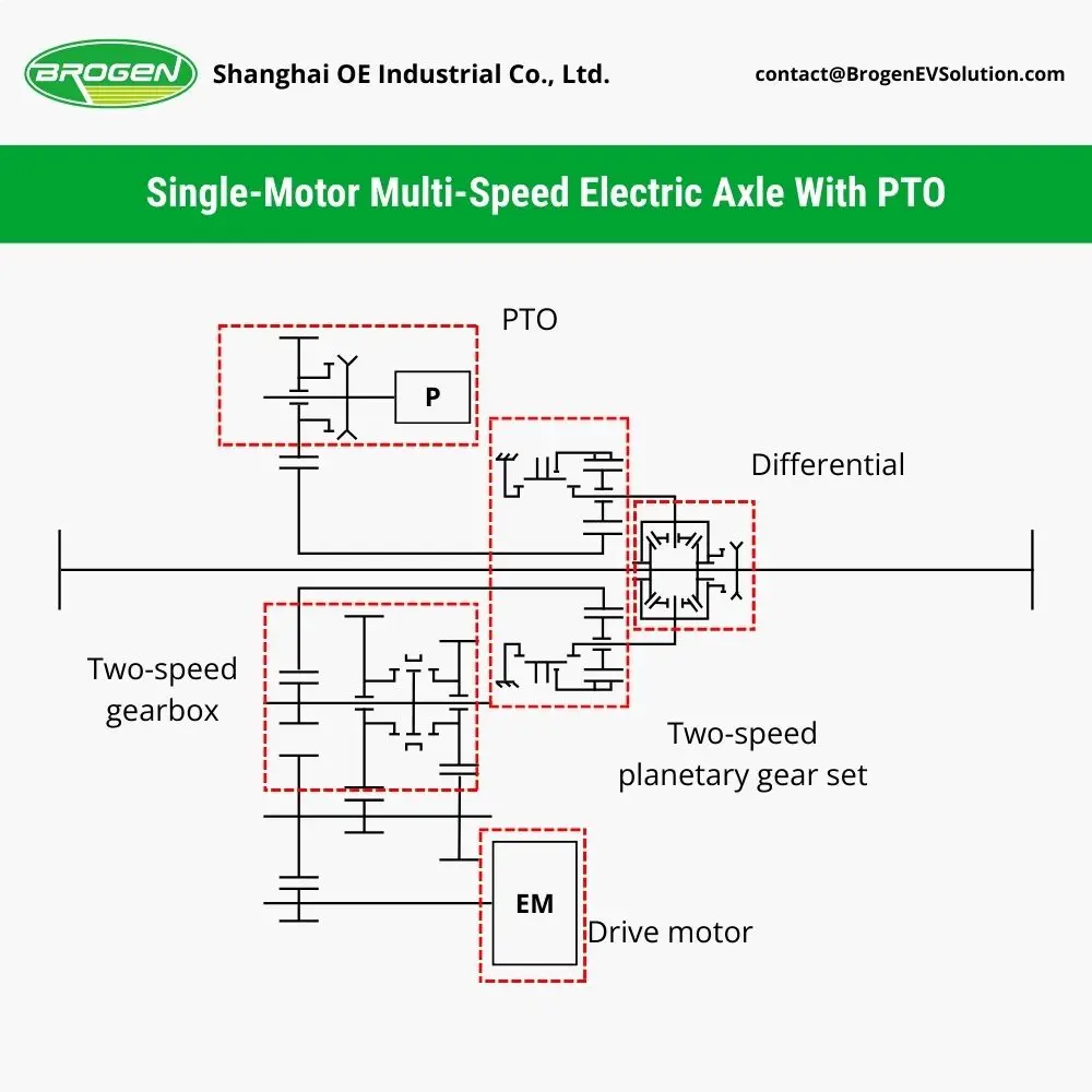
- PTO (Power Take-Off) Control: Supports operational requirements in special-use vehicles by managing PTO status, speed control, and idle conditions.
- Auxiliary Systems Management: Oversees the operation of water pumps, cooling fans, vacuum pumps, EPS motors, and air compressors.
3. Signal Output – The “Executors” of VCU Commands
This layer handles the transmission of control signals generated by the VCU to the vehicle’s actuators. The output methods include hardwired signals, CAN communication, and data storage:
- Hardwired Output: Used to enable or wake up components like the BMS, MCU, and TCU. It also provides direct control over specific functions such as pump and fan speed.
- CAN Output: Enables efficient communication with various high-voltage systems, controlling torque commands, motor speeds, generator activation, relay switching, and more.
- E-Flash Storage: Stores vital data such as mileage, learned values, and average energy consumption to support diagnostics, analytics, and long-term performance optimization.
Conclusion
By understanding the structure and function of a Vehicle Control Unit, we can better appreciate the role it plays in enabling intelligent, efficient, and safe vehicle operation. Whether it’s managing torque output, coordinating energy use, or communicating with dozens of subsystems, the VCU lies at the heart of modern vehicle control strategies.
About Brogen
At Brogen, we provide advanced EV solutions for global commercial vehicle manufacturers, enabling them to streamline research and development while capitalizing on cutting-edge technology. Our offerings ensure superior efficiency, extended range, and seamless system integration with proven reliability—empowering our partners to lead in the rapidly evolving green mobility landscape.
Currently, our EV solutions for battery electric buses and trucks have been adopted by vehicle manufacturers in countries and regions such as Australia, Türkiye, Brazil, the Philippines, Indonesia, the Middle East, and more.
- Looking for an EV solution for your project? Reach out to us at contact@brogenevsolution.com
Contact Us
Get in touch with us by sending us an email, using the Whatsapp number below, or filling in the form below. We usually reply within 2 business days.
Email: contact@brogenevsolution.com
Respond within 1 business day
Whatsapp: +8619352173376
Business hours: 9 am to 6 pm, GMT+8, Mon. to Fri.
LinkedIn channel
Follow us for regular updates >
YouTube channel
Ev systems introduction & industry insights >