Battery Electric Bus Body: Structural Design and Strength Optimization
To advance the adoption of electric vehicles and fully capitalize on the energy-saving and emission-reduction benefits of battery electric buses (BEBs), a lightweight electric bus body design is essential. This article presents an overview of topology optimization theory and explores key material options for electric bus body construction, including high-strength steel, aluminum alloys, and carbon fiber composites.
It highlights the advantages of advanced materials in improving structural performance and outlines methodologies for analyzing structural loads, optimizing topology, and ensuring strength and reliability. These insights provide valuable guidance for the development, design, and manufacturing of next-generation electric buses, supporting both performance and sustainability goals.
Introduction
The electric vehicle (EV) sector is undergoing rapid development, particularly in the public transportation segment, where battery electric buses offer significant advantages such as zero emissions, reduced operating costs, and simpler maintenance. However, one of the primary challenges hindering wider adoption is limited driving range. Reducing curb weight – while maintaining safety and structural integrity – is a proven strategy to extend range and improve overall vehicle efficiency.
Since the body structure contributes more than one-third of a bus’s total weight, lightweighting the body is a critical focus. By leveraging topology optimization theory and finite element analysis (FEA), engineers can minimize material use while maintaining required levels of stiffness and strength. This approach not only enhances vehicle range but also contributes to long-term energy efficiency and emission reduction goals.
1. Topology Optimization Principles
When applying topology optimization to electric bus body design, shape optimization techniques are used to find the most efficient material layout under one or more loading conditions. This approach targets minimum structural stiffness. It starts with developing a digital base model of the bus body, then uses optimization algorithms to remove unnecessary components while retaining critical structural elements. This improves the structural layout’s rationality and reliability.
In practice, topology optimization is performed with the following considerations:
- Analysis Type: Static analysis
- Element Types: First-order and second-order tetrahedral elements
- Material Behavior: Liner elastic, elastoplastic, hyperelastic
- Loading Conditions: Concentrated force, pressure, torque, gravity
- Boundary Conditions: Displacement constraints
- Contact Conditions: Bonded and surface contact
- Connection Types: Rigid and beam connections
- Objective Function: Maximize stiffness
- Design Variables: Topology variables
- Constraints: Volume fraction
If the total number of elements is denoted as a, then each element can be represented as y(i = 1, 2, 3, …, a). During the structural optimization process, if the h-th element is determined to be non-essential, it will be assigned a value of yₕ = 0; if it is essential and should be retained, it will be assigned yₕ = 1. The structural optimization design of a pure electric bus body can be carried out using finite element analysis (FEA) combined with variable design methods.
2. Main Types of Electric Bus Materials
The evolution of bus body materials reflects a broader shift toward lightweight and high-performance materials. Initially dominated by steel (over 90% of body structure), the industry has gradually shifted toward aluminum alloys and carbon fiber composites. This shift is driven by the demand for lightweight, energy-efficient, and low-emission vehicles.
- High-Strength Steel (HSS): Created by adding trace elements to low-carbon steel and undergoing specialized rolling processes. It offers tensile strength up to 420 N/mm² and excellent deep-drawing properties, making it a strong candidate for lightweight structural components.
- Aluminum Alloys: Compared to steel, aluminum alloys have a lower density (2.7 g/cm³), higher specific strength, good corrosion resistance, thermal stability, and recyclability. These advantages make aluminum alloys widely used for lightweight applications.
- Carbon Fiber Composites: Composed of carbon fiber bundles and resin, these materials offer exceptional high tensile strength (often over 3500 MPa), high stability, and resistance to deformation during impact. Carbon fiber composites can significantly enhance passive safety and are more than twice as durable as steel.
With increasing demand for extended range, pure electric buses have transitioned from using high-strength steel to aluminum alloy bodies, which reduce body weight by 25%-35%. Modern aluminum alloy components are often assembled using rivets and bolts rather than traditional welding, and stamped aluminum parts have replaced conventional steel panels. Aluminum alloys also offer high recyclability, with recovery rates exceeding 85% when vehicles are retired.
3. Performance and Cost of Advanced Automotive Materials
Advanced materials and manufacturing processes are key drivers of automotive innovation.
- High-Strength Steel: Offers 15%-25% higher strength than standard steel, with better balance and 20% improved corrosion resistance. However, it requires additional anti-corrosion treatments to meet durability requirements.
- Aluminum Alloys: In a 10-meter bus, switching from steel to aluminum components can reduce body weight by over 450 kg. Aluminum also provides superior thermal insulation and vibration damping compared to steel. Manufacturing methods such as hot forming, die casting, and precision machining enhance part performance and structural integrity.
- Carbon Fiber Composites: Carbon fiber’s strength and stiffness per unit weight surpass all other commonly used materials. It absorbs 4-5 times more impact energy than steel and can reduce body weight by over 40%, while enhancing safety and aesthetic appeal. However, its high cost restricts its applications to high-end or specialized vehicles.
Relative Costs:
- Steel: Lowest cost
- Aluminum Alloys: Moderate cost
- Carbon Fiber Composites: Highest cost
4. Structural Load Analysis and Topology Optimization of Battery Electric Bus Body
The structural design of a battery electric bus must comply with the requirements outlined in relevant national standards and the specific design brief. This includes determining the vehicle’s primary exterior dimensions – such as length, width, height, wheelbase, front overhang, and rear overhang – while ensuring a balanced and harmonious overall appearance.
Effective spatial arrangement of the driver’s cabin and passenger area is essential for optimal internal layout. The number, position, and minimum dimensions of passenger doors and emergency roof exits must meet the standards.
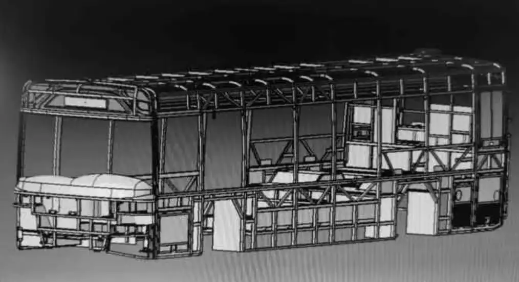
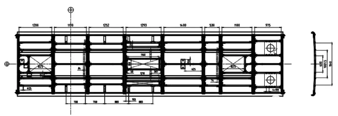
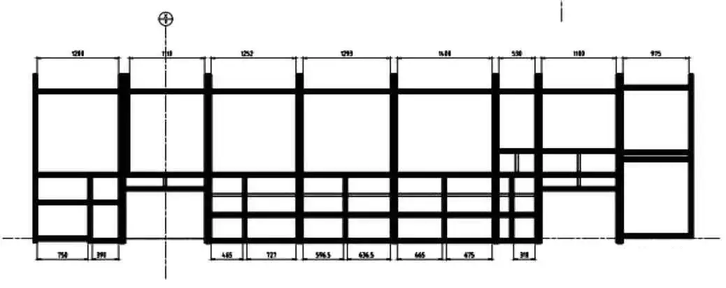
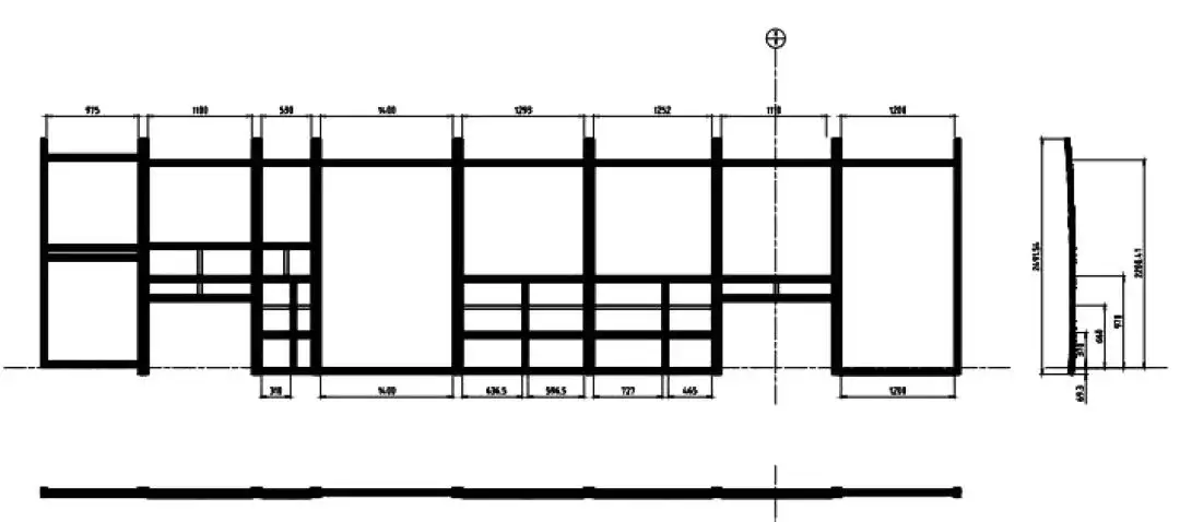
The bus body framework is composed of
several key structural assemblies: the front frame, rear frame, left and right side frames, roof frame, and underframe. During the design process, modular design principles should be adopted based on foundational 3D models. Standardized structures and components should be prioritized to minimize the need for new tooling. While ensuring structural strength and rigidity, lightweight design should be emphasized to reduce vehicle weight and control production costs.
Given the dynamic loading conditions during vehicle operation, the bus body must possess sufficient torsional rigidity, particularly around critical openings such as the windshield, side windows, and roof hatches. This ensures the longevity of glass components and prevents cracking of exterior panels. The structure must also meet strength requirements to avoid component cracking or failure throughout its service life.
Initially, high-strength steel sheets and specially shaped tubing made of Q235 steel—a material with excellent mechanical and metallurgical properties—were widely used in bus body structures. Currently, there is a gradual shift toward aluminum alloy materials to further reduce weight.
Design accuracy is another critical consideration. Dimensional data should follow the principle: Nominal Value = Theoretical Value + Tolerance. For components requiring template verification, the theoretical dimension precision should be up to 0.1 mm. For components not requiring templates, a precision of 1 mm is acceptable, with a minimum deviation unit also of 1 mm.
The overall vehicle design must also consider environmental conditions (e.g., extreme heat, cold, desert, and coastal climates), road types (e.g., plains, hills, mountains), cultural preferences, regional passenger behaviors, usage scenarios, and local regulations. Leveraging base CAD models, the bus body should be divided into multiple substructures. Based on the vehicle’s functional characteristics and operational conditions, a fully constrained design methodology should be adopted, followed by topology optimization to ensure a scientifically sound and efficient structure.
When analyzing the results of topology optimization, attention should be given to the load density distribution of body components. The goal of topology optimization is to maintain structural integrity while minimizing material usage. Once the structural design is complete, thorough validation and design reviews are required to ensure compliance with performance and safety standards.
5. Structural Design and Strength Analysis of Electric Buses
Bus bodies generally fall into two categories: body-on-frame (non-load-bearing) and monocoque (load-bearing) structures. The monocoque structure is becoming the mainstream approach in new energy bus design. In this configuration, the bus body is constructed using small cross-section shaped tubes to form an integrated load-bearing system.
For monocoque bodies, strength-based design principles are applied, focusing on the structural strength of each member to ensure overall performance. In contrast, non-load-bearing bodies primarily require adequate stiffness; once stiffness is ensured, static and fatigue strength are usually also satisfactory. Therefore, non-load-bearing structures are typically controlled by stiffness design, while monocoque bodies rely on strength theory.
In stiffness-controlled designs, each component must independently meet strength and stiffness requirements, which often leads to material overuse and limits weight reduction. Conversely, strength-controlled monocoque designs allow the overall stiffness to be achieved through optimal structural arrangements. As long as individual components meet strength criteria, the entire structure will comply, enabling significant material savings and greater opportunities for lightweighting.
During the design of new energy bus bodies, enhancing overall rigidity—especially in the passenger cabin—is critical for ensuring safety. The structure should form one or more rigid load-bearing rings, particularly around the key cross-sections at the front and rear suspension points. Two common configurations of rigid ring structures are large and small closed-loop frames. Integrating the body components into a unified structure reduces manufacturing complexity and enhances structural strength.
Topology optimization techniques can effectively ensure a tightly integrated and rigid body structure, minimizing stress concentration and improving overall frame rigidity. The optimized body frame can be evaluated through static strength analysis using software such as HyperMesh. The material properties and mechanical performance must comply with relevant standards while meeting all design criteria.
6. Conclusion
Achieving lightweight design in battery electric buses, without compromising structural safety, is essential for improving energy efficiency and reducing emissions. Structural optimization – especially through topology optimization methods – plays a key role in reaching this goal. By applying these methods early in the design phase, high-quality solutions can be developed to support vehicle development, engineering, and manufacturing. This approach lays a solid foundation for creating safe, reliable, and efficient battery electric buses.
About Brogen
At Brogen, we provide advanced EV solutions for global bus manufacturers, enabling them to streamline research and development while capitalizing on cutting-edge technology. Our offerings ensure superior efficiency, extended range, and seamless system integration with proven reliability—empowering our partners to lead in the rapidly evolving public transport landscape.
Currently, our EV solutions for battery electric buses have been adopted by bus manufacturers in countries and regions such as Australia, Türkiye, Brazil, the Philippines, Indonesia, the Middle East, and more.
- Explore our public transport electrification solution here: https://brogenevsolution.com/public-transport-electrification-solutions/
- Looking for an EV solution for your project? Reach out to us at contact@brogenevsolution.com
Contact Us
Get in touch with us by sending us an email, using the Whatsapp number below, or filling in the form below. We usually reply within 2 business days.
Email: contact@brogenevsolution.com
Respond within 1 business day
Whatsapp: +8619352173376
Business hours: 9 am to 6 pm, GMT+8, Mon. to Fri.
LinkedIn channel
Follow us for regular updates >
YouTube channel
Ev systems introduction & industry insights >