Battery Thermal Management for Electric Buses: An Overview
This article explores the structure and working principles of common battery thermal management in battery electric buses (BEB), offering valuable insights for their design. The performance of the traction battery system is a key factor in a battery electric bus’s overall efficiency, range, and reliability. Since battery temperature directly affects performance, lifespan, and safety, a well-designed thermal management system is crucial for optimizing operation and ensuring long-term durability.
1. Different Types of Battery Thermal Management
Effective battery thermal management ensures optimal performance and safety by regulating temperature under varying conditions. This includes cooling the battery during high temperatures to prevent overheating and heating it in low temperatures to maintain efficiency and reliability.
1.1 Battery Cooling Methods
Battery cooling is essential for maintaining performance and safety in electric buses. The most common cooling methods for EV batteries include natural air cooling, forced air cooling, liquid cooling, and direct refrigerant cooling.
The air cooling method features a simple structure, lightweight design, low cost, and no risks of harmful gas accumulation or liquid leakage. However, its drawbacks include low heat dissipation efficiency, difficulty in sealing design, and poor dustproof and waterproof performance. Depending on whether additional devices are used to introduce cooling air, the air cooling system is divied into natural air cooling and forced air cooling:

- Natural Air Cooling: It’s a method of utilizing the wind generated by the vehicle’s movement to flow through a diversion pipe and directly cool the battery pack. This approach requires no auxiliary motors, offers a simple structure, and is easy to use. However, the cooling airflow is subject to instability due to fluctuations in vehicle speed, resulting in variable cooling performance. Additionally, air has low heat capacity and thermal conductivity, which limits the efficiency of heat transfer. Natural air cooling is best suited for vehicles with low discharge rates and minimal heat generation in their power batteries.
- Forced Air Cooling: It directly introduces cabin air, natural air, or external convection air into the battery compartment to cool the battery pack. This cooling method has relatively poor performance, the largest system volume, and a high risk of water ingress. However, it is lightweight, easy to control, has low energy consumption, relatively low system costs, is relatively easy to implement, and offers high process reliability.

- Liquid Cooling: It utilizes convective heat transfer through a coolant to dissipate the heat generated by the battery, effectively lowering its temperature. It’s currently the most widely adopted cooling solution in the market. Compared to air cooling, liquid cooling systems – using coolant as the heat transfer medium – offer significantly higher specific heat capacity and thermal conductivity. Additionally, in low-temperature environments, the system can also provide heating for the battery pack. However, the primary drawbacks of liquid cooling include increased structural complexity, added battery system weight, and higher overall system costs.

- Direct Refrigerant Cooling: Also known as direct cooling or refrigerant-based cooling, integrates the battery thermal management system with the vehicle’s air conditioning system. In this approach, an evaporator in the refrigerant loop functions as the battery’s direct cooling plate, simplifying the overall system. It minimizes heat exchange losses, resulting in a rapid thermal response. And the design eliminates the need for a separate battery cooling loop, reducing components like the coolant pump, piping, and chiller, leading to a more space-efficeint, lightweight thermal management system.
A comparison of different cooling methods is as follows:
| Comparison Item | Natural Cooling | Forced Air Cooling | Liquid Cooling | Direct Cooling |
| Working Principle | Natural air convection | Forced air convection | Forced liquid convection | Phase-change cooling |
| Heat Transfer Coefficient (W/m²K) | 5-25 | 25-100 | 500-15000 | 2500-25000 |
| Heat Dissipation Efficiency | Poor | High | High | Very High |
| Temperature Uniformity | Good without external heat sources, otherwise poor | Poor (especially at inlet and outlet) | Good | Good |
| Installation Environment Adaptability | Poor (requires external insulation and ventilation) | Fair (dependent on inlet and outlet air structure) | Good | Good |
| Suitability for High/Low Temperatures | Poor (conflict between auxiliary heating/insulation and heat dissipation) | Poor (conflict between auxiliary heating/insulation and heat dissipation) | Good (capable of both heating and cooling) | Poor (requires additional auxiliary heating, difficult to control heat pump) |
| Complexity | Simplest | Moderate | Complex | Complex |
| Energy Consumption | None | High | Low (easy to implement insulation) | Low (high efficiency) |
| Cost | Low | Relatively High | High (can be optimized) | High |
1.2 Battery Heating Methods
To maintain optimal performance in cold conditions, EV traction batteries require heating. The most common battery heating methods include:
- Integrated Electric Heating Film: A thin electric heating film integrated inside the battery pack directly heats the battery cells.
- Performance: Above 0°C: works well, requires no additional space, consumes no energy when inactive, and is cost-effective. Below 0°C: heating efficiency drops significantly, making it unsuitable for extremely cold environments.
- Advantages: Space savings and easy to implement; low system cost and no additional control needed.
- Limitations: Ineffective in freezing temperatures, leading to limited adoption in colder climates.
- Liquid-Based Heating System: An electric liquid heater is integrated into the thermal management system’s coolant circuit to heat the antifreeze, which then circulates to warm the battery pack.
- Performance: Provides efficient and uniform heating, making it the preferred method in colder regions.
- Advantages: Compact system design with minimal space requirements; mature and reliable technology with well-established control mechanisms; high heating efficiency, ensuring stable battery operation in low temperatures
- Limitations: Higher system cost compared to electric heating films.
| Comparison Item | Electric Heating Film | Liquid Heating |
| Heating Characteristics | Constant power heating | Convective/conductive heating |
| Space constraints (Thickness) | 0.3~2 mm | Integrated into the liquid heating system |
| Heating Rate | 0.15~0.3°C/min | 0.3~0.6°C/min |
| Uniformity (Battery Temperature Difference) | ≈8°C | ≤5°C |
2. Structure and Working Principles of Battery Thermal Management Systems
To maintain optimal performance and longevity, EV traction batteries in electric buses operate within an ideal temperature range of 25°C ± 5°C, regardless of seasonal variations. In winter, the battery thermal management system heats the coolant to maintain the target temperature of 25°C ± 5°C. In summer, the system cools the coolant to the same temperature range to prevent overheating.
Electric buses commonly use three types of liquid-based thermal management systems, which integrate both heating and cooling functions. These systems adjust the battery temperature based on environmental conditions and operational needs:
- Cooling Mode: When cooling is required, the heat exchanger in the battery thermal management system lowers the temperature of the antifreeze coolant.
- Heating Mode: When heating is needed, a PTC electric liquid heater integrated into the thermal management circuit warms the antifreeze, which then circulates to heat the battery pack.
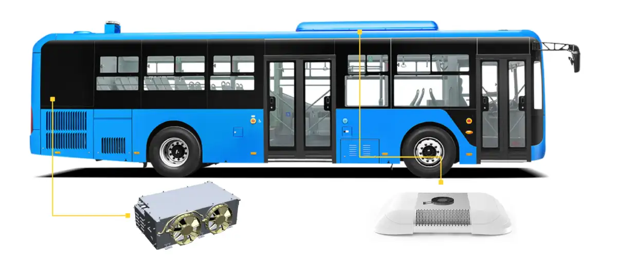
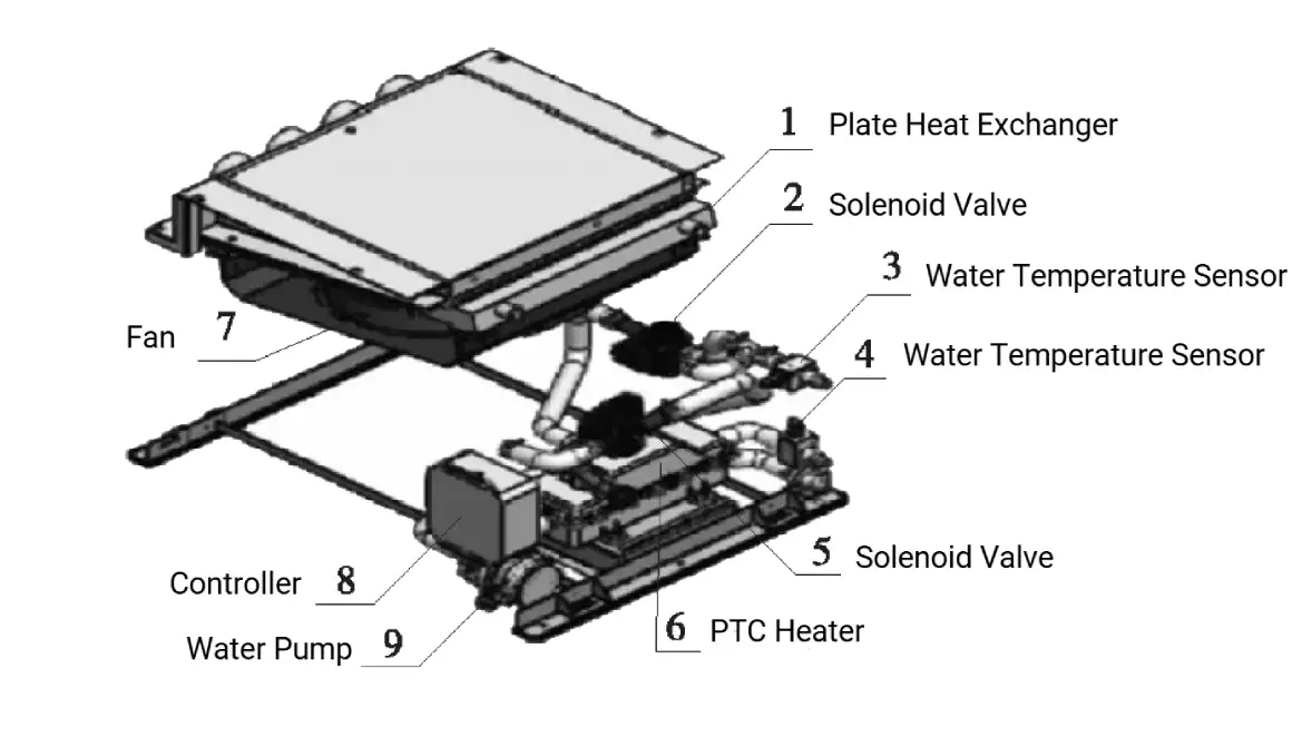
2.1 Basic Unit Configuration
A basic battery thermal management system (BTMS) consists of the plate heat exchanger, water pump, fan, and PTC electric liquid heater.
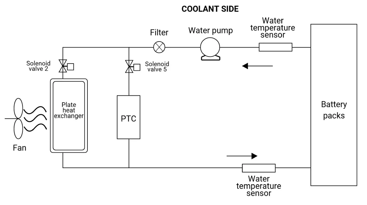
When the basic BTMS receives a cooling signal:
- Solenoid valve 2 opens, solenoid valve 5 closes, and the fan and water pump start operating.
- Cool air is drawn from the air conditioning duct through the air intake pipe.
- The cool air passes through the plate heat exchanger where it exchanges heat with the antifreeze coolant in the system.
- The cooled antifreeze coolant is then pumped into the battery heat exchanger, lowering the battery temperature.
When the system receives a heating signal:
- Solenoid valve 2 closes, solenoid valve 5 opens, and the PTC electric liquid heater and water pump start working.
- The heater warms the antifreeze coolant, which then flows into the battery’s internal heat exchanger.
- The heat is transferred to the battery pack, raising its temperature.
In addition to heating and cooling, the water-cooled unit also features a self-circulation function, which helps regulate temperature differences within the battery pack.
- When the Battery Management System (BMS) sends a self-circulation command, the PTC heater and fan stop, while the water pump continues operating.
- The antifreeze coolant circulates within the system, preventing large temperature differences inside the battery pack.
The basic BTMS unit is simple in structure and relatively inexpensive. However, because it lacks an independent refrigeration system and relies on cool air from the cabin for cooling, it has limited cooling capacity. Additionally, its cooling performance depends on the air conditioning system, which restricts its application. Due to its low cooling power (typically less than 2 kW), this system is suitable for hybrid buses with slow-charging batteries that operate at low charge-discharge rates.
2.2 Non-Independent Unit Configuration
A non-independent battery thermal management system integrates with the vehicle’s air conditioning system to manage battery temperature.
- Evaporator 1: Part of the air conditioning system, used for cooling the passenger cabin.
- Ecaporator 2: A dedicated water-cooled evaporator for the battery system, where antifreeze coolant exchanges heat with the refrigerant to lower its temperature, thereby cooling the battery.
Both evaporators are arranged in parallel, sharing a common compressor, condenser, and dryer bottle. The refrigerant flow is managed as follows:
- Solenoid Valve 1 and Solenoid Valve 2 control the refrigerant distribution to each evaporator.
- Expansion Valve 1 and Expansion Valve 2 regulate the refrigerant flow for each circuit.
Operation Modes
- Battery Heating Mode
- Solenoid Valve 2 closes.
- The water pump and PTC electric liquid heater activate.
- The PTC heater warms the antifreeze coolant, which is then circulated to the battery’s internal heat exchanger to raise its temperature.
- Self-Circulation Mode
- Solenoid Valve 2 closes.
- The PTC heater stops operating, but the water pump continues running.
- The system circulates coolant internally to maintain uniform battery temperature and prevent large temperature variations.

The non-independent unit does not require a separate cooling system, which helps reduce the cost of thermal management equipment. However, it has several limitations:
- Impact on Passenger Cooling: since the non-independent unit diverts part of the refrigerant from the air conditioning system, it can reduce cooling efficiency in the passenger area. This also increases the load on the air conditioning system.
- Energy Efficiency Issues: The long high- and low-pressure refrigerant pipelines between the air conditioning system and the battery water-cooling unit reduce the overall energy efficiency of the air conditioning system.
- Integration Challenges: Bus manufacturers use different air conditioning suppliers and models, making it difficult to standardize the compatibility between the water-cooling unit and the air conditioning system. This is a key factor limiting the adoption of non-independent units.
- Application Scope: Higher cooling capacity (typically above 6 kW), making it suitable for fast-charging batteries with high charge/discharge rates. However, since the bus’s overall cooling demand conflicts with the battery thermal management system, the control logic is more complex, making it better suited for pure electric buses with high charging and discharging efficiency.
2.3 Independent Unit Configuration
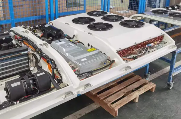
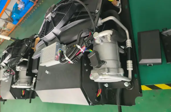
An independent unit functions as a small-scale, fully electric air conditioning system, with a complete, self-contained refrigeration system.
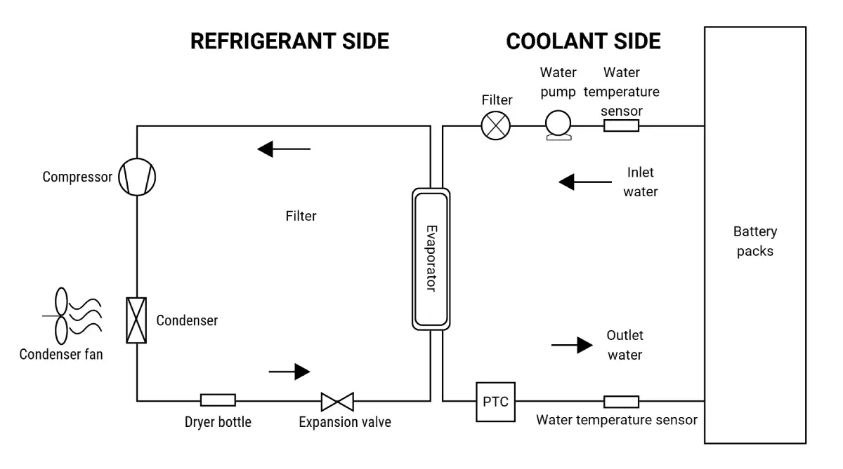
The independent unit for battery thermal management differs significantly from a standard air conditioning system, especially in terms of its evaporator structure. In a traditional air conditioning system, the evaporator is designed to facilitate heat exchange between the refrigerant and the air. However, in the independent unit, the evaporator is designed for heat exchange between the refrigerant and the antifreeze.
This specialized heat exchanger typically uses a double-tube structure, with refrigerant flowing through the inner tube and the antifreeze flowing through the outer tube. Fins are placed between the two tubes to increase the surface area for enhanced heat transfer. The independent unit can feature either an integrated or split design for the evaporator and condenser.
The independent BTMS unit requires its own dedicated refrigeration setup. When the system receives a cooling signal, the fan and pump activate, and the refrigerant flows through the heat exchanger, where it transfers heat to the antifreeze circulating in the system. The antifreeze is then pumped into the battery’s internal heat exchanger to reduce the battery temperature. When heating is needed, the PTC electric liquid-type heater and pump within the unit activate, heating the antifreeze. The antifreeze then exchanges heat with the internal heat exchange plates of the battery to raise its temperature.
One of the key advantages of the independent unit is its ability to be designed for specific power requirements, with matching components such as compressors and evaporators, to accommodate different cooling needs. This makes the independent unit more versatile compared to non-independent units. Additionally, it responds more quickly to changes in the battery’s internal temperature and does not require consideration of the air conditioning performance in the passenger area, offering greater flexibility in placement. However, because the independent unit includes a separate compressor and condenser for refrigeration, it comes at a higher cost. Despite this, its standalone system design makes its control logic simpler and more straightforward than that of a non-independent unit.
The cooling capacity of the independent unit can be selected according to specific needs, typically starting at 2 kW or higher, making it well-suited for hybrid and pure electric buses that utilize high charge/discharge rate batteries.
3. Conclusion
The battery thermal management system is a crucial component of electric buses, effectively ensuring the performance, safety, and longevity of the power battery. Therefore, it is essential to have a thorough understanding of the structure and working principles of the battery thermal system equipment during the design process.
At Brogen, we provide battery thermal management solutions for all types of commercial vehicles, including electric buses, trucks, and even construction equipment.
Learn more here: https://brogenevsolution.com/battery-thermal-management-system-btms/
Business inquiry: contact@brogenEVSolution.com
Solution features:
- Modular Design
- Simplifies vehicle integration, assembly, and debugging.
- Improves overall system efficiency.
Advanced Refrigeration System
- Uses a high-efficiency DC inverter compressor with PID automatic adjustment for dynamic temperature control.
- Supports automatic variable frequency operation for both high and low temperatures.
Efficient Heating System
- Equipped with a power-adjustable PTC heater to handle defrosting, defogging, and cabin heating.
- Built-in temperature protection ensures automatic shutdown in case of overheating or abnormal conditions, enhancing safety.
Smart Liquid Cooling System
- Embedded intelligent modules optimize cooling performance while minimizing power consumption in low temperatures.
- Adaptive flow and water temperature control ensure efficient heat dissipation.
Seamless Vehicle Integration
- CAN communication enables real-time interaction with the vehicle system.
- User-friendly control panel displays cabin and ambient temperatures for easy monitoring.
Adaptive Environmental Control
- Designed to function effectively in high-altitude regions and extreme weather conditions.


Contact Us
Get in touch with us by sending us an email, using the Whatsapp number below, or filling in the form below. We usually reply within 2 business days.
Email: contact@brogenevsolution.com
Respond within 1 business day
Whatsapp: +8619352173376
Business hours: 9 am to 6 pm, GMT+8, Mon. to Fri.
LinkedIn channel
Follow us for regular updates >
YouTube channel
Ev systems introduction & industry insights >