Battery Thermal Management System (BTMS) for Electric Buses: Selection and Integration Strategy
This article introduces common types and configurations of battery thermal management systems (BTMS) for electric buses. As a critical component of electric buses, the BTMS acts as a “guardian” for the battery, ensuring its performance, safety, and longevity. Therefore, a thorough understanding of the different BTMS types and layouts is essential for practical applications.
1. Selection of the Battery Thermal Management System (BTMS) for Electric Buses
The battery thermal management system (BTMS) for electric buses regulates the battery’s operating temperature through external equipment, ensuring that the battery always functions within an optimal temperature range. For lithium batteries, the ideal working temperature is between 20°C and 35°C.
When the temperature is too low, battery capacity decreases, and power performance declines. When the temperature is too high, the risk of self-discharge increases, and internal side reactions become more frequent, reducing the available battery capacity and decreasing its lifespan and efficiency.
Battery thermal management involves cooling the battery in summer to prevent irreversible thermal reactions that could cause safety issues. In winter, it heats the battery to maintain charging and discharging performance while preventing lithium plating at the anode, which could lead to internal short circuits.
The selection of battery thermal management equipment should be based on the vehicle’s operating conditions and battery placement to meet the thermal management requirements. Ensuring that the battery remains in an optimal “comfort zone” helps improve its lifespan. Below are common battery thermal management solutions for buses.
1.1 Basic Battery Thermal Management System
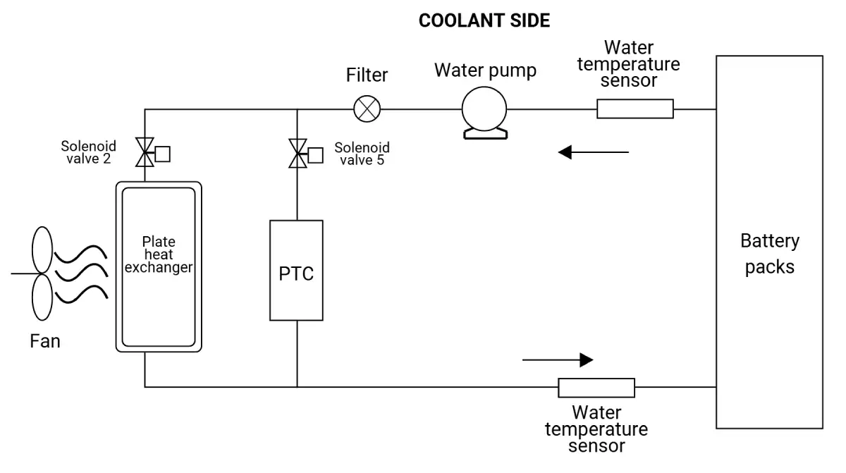
The basic BTMS unit directs air-conditioned cold air into the unit to exchange heat with circulating antifreeze for cooling. For heating, it uses an electric liquid heater to warm the antifreeze, which is then circulated to the battery pack. After cooling or heating, the antifreeze enters the battery compartment to regulate the battery’s temperature, keeping it within the desired range.
Compared to independent and non-independent BTMS units, the basic unit is the most cost-effective and simplest system. It is also relatively safe, as it does not use a vapor compression refrigeration cycle. However, since it relies on the vehicle’s air conditioning system for cooling, it requires the installation of a cooling system. Additionally, when the cooling system first starts, the cold air temperature is relatively high, leading to poor initial cooling performance.
The cooling power is generally below 2 kW, making this solution suitable for hybrid buses with slow-charging battery packs and low charge/discharge rates.
1.2 Independent Battery Thermal Management System
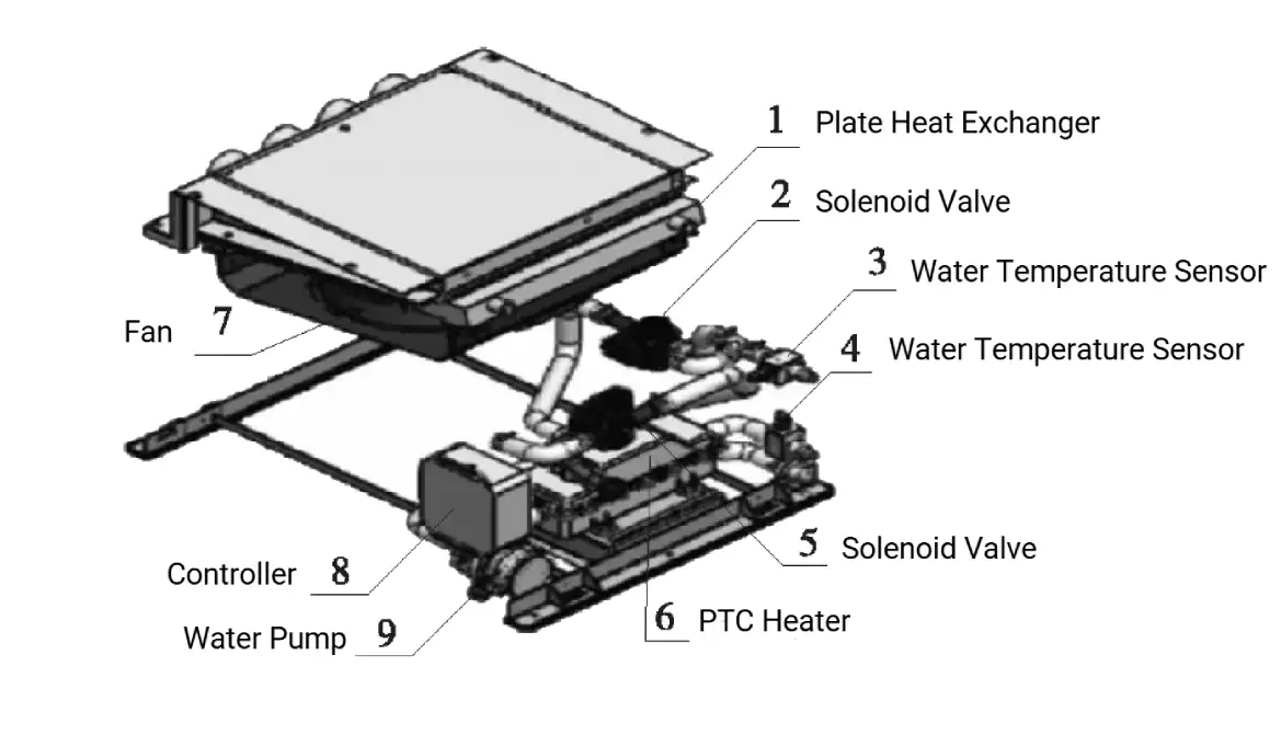
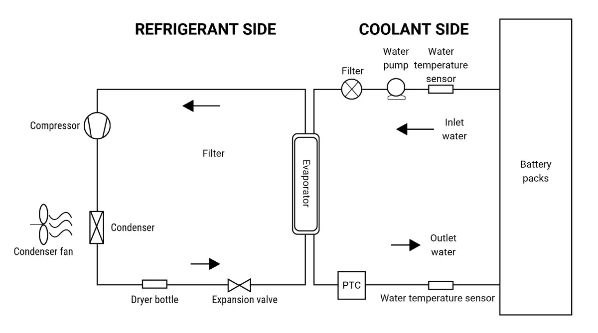
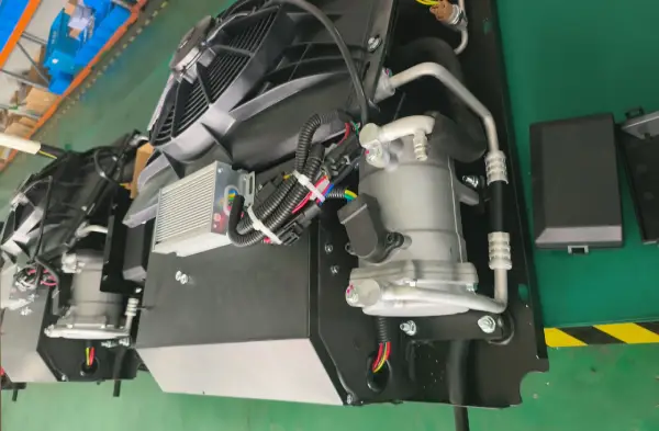
The independent BTMS unit includes its own compressor, condenser, and plate heat exchanger, forming a separate cooling cycle. Cooling is achieved by exchanging heat between low-temperature, low-pressure refrigerant and the circulating antifreeze in the heat exchanger. Heating is done via an electric liquid heater that warms the antifreeze before circulating it to the battery pack.
Compared to the non-independent unit, this system has an additional dedicated compressor and condenser, increasing costs. However, since it operates independently, it features simpler control logic and fewer refrigerant connectors, making it relatively safer.
The cooling power of an independent unit is generally above 2 kW, making it suitable for hybrid and fully electric buses with fast-charging battery packs and high charge/discharge rates.
1.3 Non-Independent Battery Thermal Management System
The non-independent BTMS utilizes an external cooling system, where low-temperature, low-pressure refrigerant produced by another cooling device exchanges heat with circulating antifreeze in a plate heat exchanger. Heating is performed using an electric liquid heater, which warms the antifreeze before it circulates to the battery pack.
Since it shares the vehicle’s cooling system, it requires the installation of a refrigeration system. Additionally, due to the variable-frequency compressor’s minimum frequency limit, the power output is relatively high, typically above 6 kW.
Compared to an independent unit, this system has a more complex control logic due to potential conflicts between battery thermal management and vehicle air conditioning demands.
The non-independent unit is suitable for fully electric buses with fast-charging battery packs and high charge/discharge rates.

2. Layout of Battery Thermal Management System for Electric Buses
2.1 Basic Principles for BTMS Layout
The layout of battery thermal management equipment is closely related to the placement of the battery itself. The following principles should be followed when arranging the equipment:
- Proximity to the battery placement – The thermal management equipment should be installed as close as possible to the battery, whether the battery is mounted on the top, bottom, or rear of the vehicle. At the same time, potential disadvantages associated with the chosen placement should be minimized.
- Installation requirements for different types of equipment – For independent battery thermal management systems, vibration-damping rubber pads should be added during installation. The condenser’s air intake and exhaust must remain unobstructed to prevent air recirculation. For basic thermal management systems, cold air should be drawn from the vehicle’s refrigeration system. The air intake point should be positioned as close as possible to the evaporator outlet of the main cooling system.
- Coolant circulation considerations – The water pump inlet for circulating antifreeze through the battery box’s cooling plate should be located as close as possible to the expansion tank, which maintains system pressure and allows antifreeze refilling. The expansion tank must be placed at the highest point of the battery cooling system. Additionally, an air vent pipe should be included to remove air released during heating or cooling, preventing difficulties in adding antifreeze.
- Cooling circuit for multiple battery groups – To minimize temperature differences between different battery packs, the cooling circuit should be arranged in a parallel configuration. Each individual branch should not exceed three battery boxes per loop.
- PTC Electric Liquid Heater Placement – If a PTC electric liquid heater is installed, it should be positioned downstream of the water pump at a lower point in the cooling circuit. It must not be placed at the highest point of the coolant loop.
- Optimization of coolant piping – The pipes should be as short as possible with large turning radii to reduce flow resistance. Insulation should be applied to minimize heat loss during antifreeze circulation. Pipe connectors should be made of stainless steel or nylon, and copper should not be used to prevent corrosion of the cooling plates inside the battery box, ensuring no coolant leakage occurs.
- Ease of maintenance – The layout should facilitate easy access for inspection and repairs of the thermal management equipment.
A general schematic diagram of battery thermal management is shown below.

2.2 Advantages and Disadvantages of Different Layouts
2.2.1 Roof-Mounted Layout of BTMS for Electric Buses
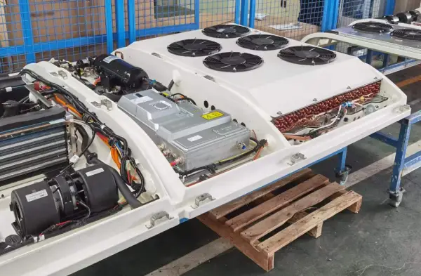
The following picture shows the top-mounted layout of an independent battery thermal management system in a pure electric bus. The system includes a cooling unit, water-cooling circulation system, electric liquid heater, and water pump, all installed on a roof-mounted support frame along with the battery pack. The support frame is fixed to the roof using pre-installed bolts embedded in the roof skeleton.

In the design process, it is important to ensure that the water pump is positioned at the lowest point of the coolant circuit, while the expansion tank has a significant height difference from the coolant system to optimize coolant flow. Since the support frame is removable, the thermal management system and its piping can be assembled on the ground before being lifted and secured onto the roof. This allows for a larger working space during assembly, improving efficiency.
One of the key benefits of a top-mounted layout is that the equipment is placed in a cleaner air environment, reducing the accumulation of dust on the condenser surface and preventing efficiency loss in heat dissipation. Additionally, this layout does not interfere with the vehicle’s internal structure, making it more flexible in terms of system integration. Furthermore, keeping the cooling pipes mostly on the same plane minimizes resistance and ensures uniform water flow through all battery packs, helping to maintain battery temperature consistency.
However, a top-mounted layout also has drawbacks. It increases the load on the roof and side frames, requiring a stronger body structure to support the additional weight. It also raises the vehicle’s center of gravity, which can negatively impact stability. Finally, adding equipment to the roof may increase the risk of exceeding height restrictions, which could be a limitation for some road conditions.
2.2.2 Bottom-Mounted Layout of BTMS for Electric Buses
The following picture illustrates a bottom-mounted layout, where the cooling unit, water-cooling circulation system, and water pump are all fixed to the chassis, with coolant piping routed underneath.

One major advantage of this layout is that it lowers the vehicle’s center of gravity, enhancing stability. It also keeps the exterior design sleek, as the thermal management system is hidden underneath the vehicle. Additionally, this layout does not interfere with rooftop components, such as air conditioning units or sunroofs, providing more flexibility in vehicle design.
Despite these advantages, there are some notable disadvantages. Since coolant piping must pass through the chassis, the height differences in the coolant circuit become uneven, increasing resistance and reducing the consistency of water flow through different battery packs. Poor layout design may result in temperature imbalances between batteries. Additionally, the limited space in the chassis makes installation more complex and requires modifications to the vehicle’s body and frame.
Another key concern is that high-voltage components are located at the bottom, which means the system must be designed to withstand water exposure when the vehicle operates in wet conditions. Finally, the tight space makes maintenance and repairs more difficult, as technicians have less access to the system compared to other layouts.
2.2.3 Rear-Mounted Layout of BTMS for Electric Buses
The following picture shows a rear-mounted layout in a hybrid bus, where the cooling unit, water-cooling circulation system, electric liquid heater, and water pump are integrated with the battery pack in the rear compartment of the vehicle.

One advantage of this layout is that it does not affect the vehicle’s exterior design. Additionally, maintenance is more convenient, as the rear compartment provides easier access for servicing and repairs. Another benefit is that, compared to a bottom-mounted system, a rear-mounted system is less exposed to ground heat, and compared to a top-mounted system, it is less affected by solar radiation. This means that the external heat load is lower, helping to maintain more stable operating temperatures for the battery and thermal management system. Furthermore, unlike the bottom-mounted layout, this setup does not impact the vehicle’s ability to drive through deep water, as high-voltage components are kept away from potential water exposure.
However, the rear-mounted layout also has disadvantages. Since the thermal management system and battery pack take up space in the rear compartment, it reduces the available space for passengers. Additionally, placing heavy equipment at the rear affects axle load distribution, which may impact vehicle balance and handling.
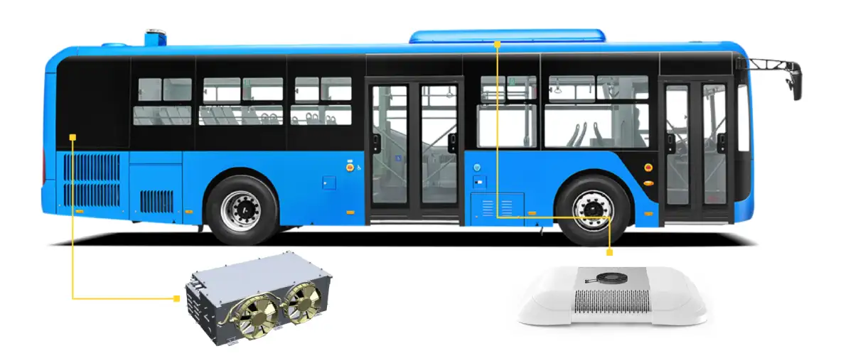
3. Our Battery Thermal Management Solution for Electric Vehicles
At Brogen, we provide battery thermal management solutions for all types of commercial vehicles, including electric buses, trucks, and even construction equipment.
Learn more here: https://brogenevsolution.com/battery-thermal-management-system-btms/
Business inquiry: contact@brogenEVSolution.com
Solution features:
- Modular Design
- Simplifies vehicle integration, assembly, and debugging.
- Improves overall system efficiency.
Advanced Refrigeration System
- Uses a high-efficiency DC inverter compressor with PID automatic adjustment for dynamic temperature control.
- Supports automatic variable frequency operation for both high and low temperatures.
Efficient Heating System
- Equipped with a power-adjustable PTC heater to handle defrosting, defogging, and cabin heating.
- Built-in temperature protection ensures automatic shutdown in case of overheating or abnormal conditions, enhancing safety.
Smart Liquid Cooling System
- Embedded intelligent modules optimize cooling performance while minimizing power consumption in low temperatures.
- Adaptive flow and water temperature control ensure efficient heat dissipation.
Seamless Vehicle Integration
- CAN communication enables real-time interaction with the vehicle system.
- User-friendly control panel displays cabin and ambient temperatures for easy monitoring.
Adaptive Environmental Control
- Designed to function effectively in high-altitude regions and extreme weather conditions.


Contact Us
Get in touch with us by sending us an email, using the Whatsapp number below, or filling in the form below. We usually reply within 2 business days.
Email: contact@brogenevsolution.com
Respond within 1 business day
Whatsapp: +8619352173376
Business hours: 9 am to 6 pm, GMT+8, Mon. to Fri.
LinkedIn channel
Follow us for regular updates >
YouTube channel
Ev systems introduction & industry insights >