How to Choose the Right Electric Truck Motor in 2026: Oil-Cooled vs. Water-Cooled
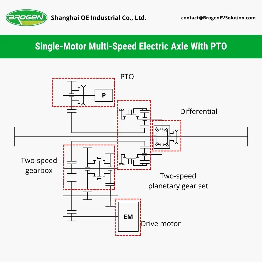
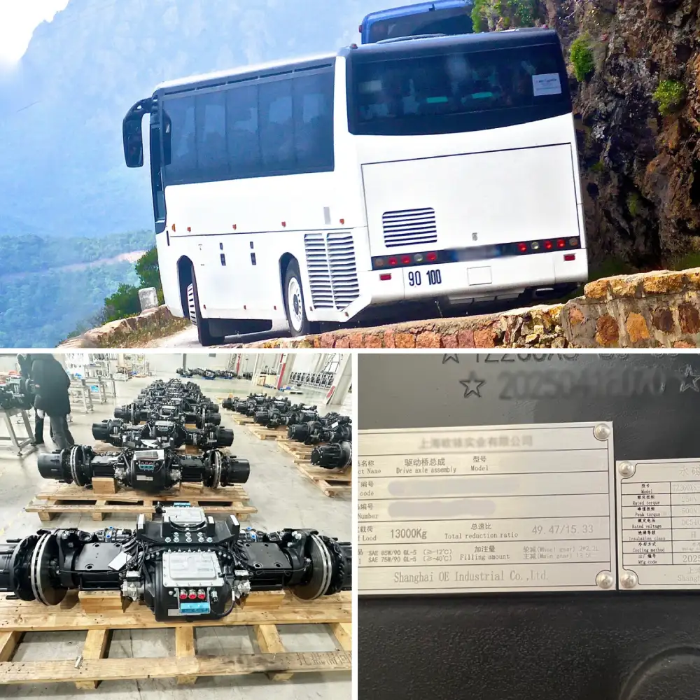
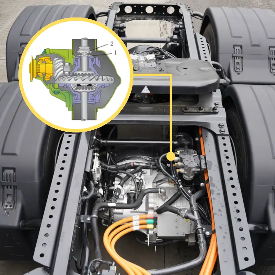
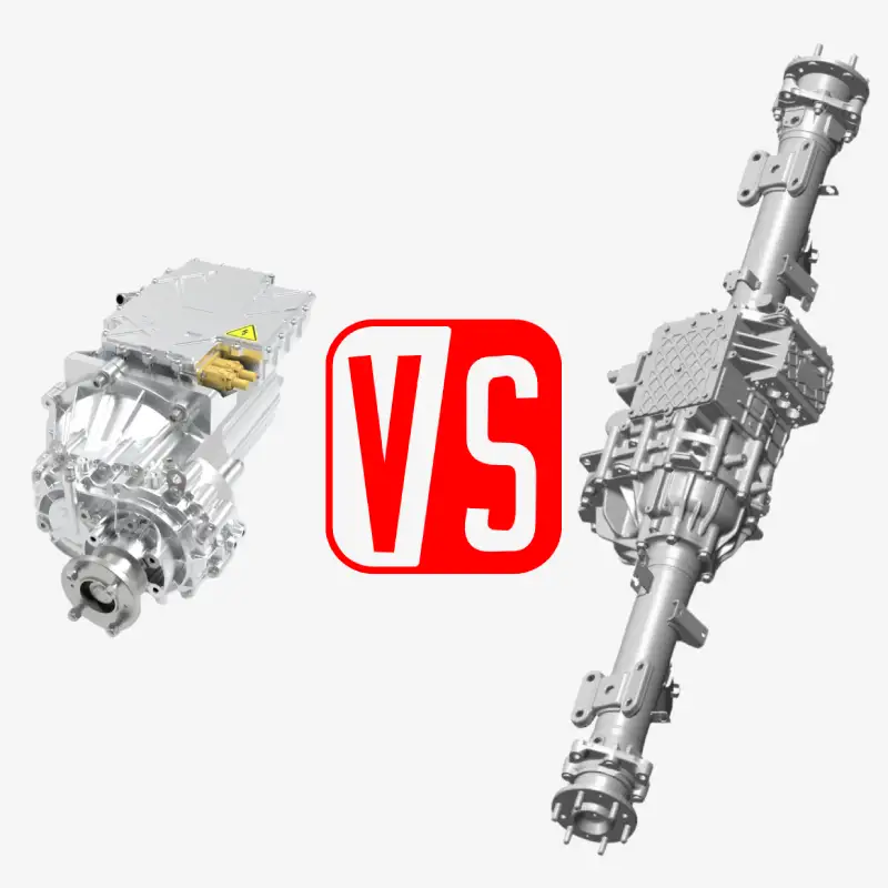
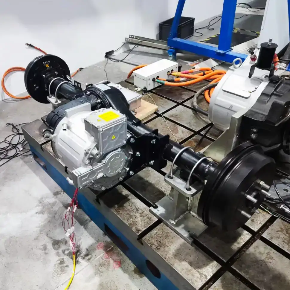
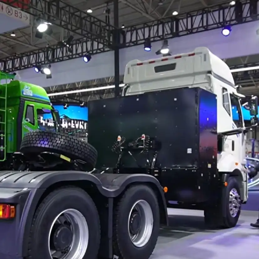
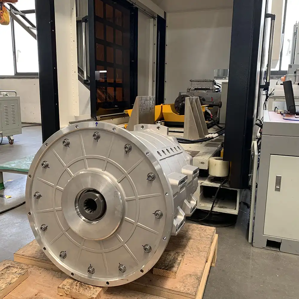
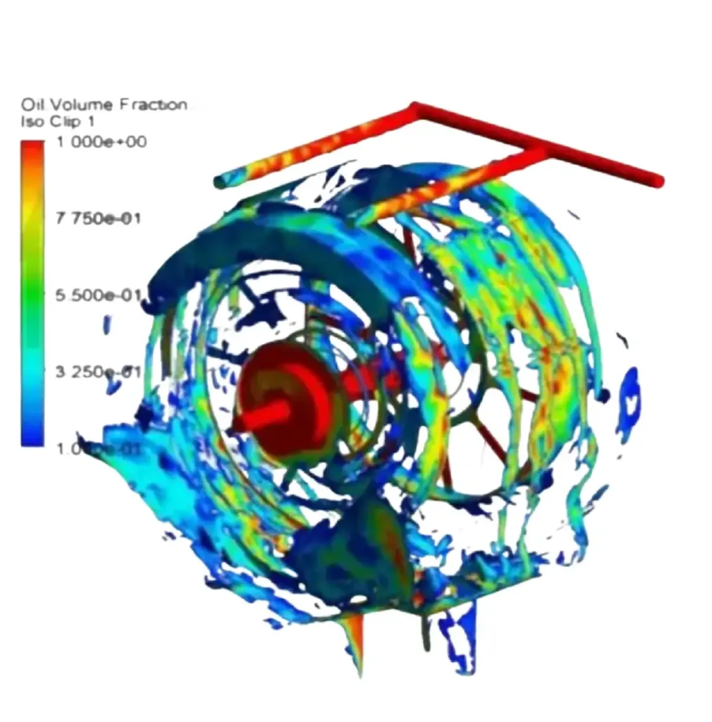
Choosing the Right Electric Truck Motor in 2026: Oil-Cooled vs. Water-Cooled Solutions Oil-cooled electric truck motors have become a frequent topic in product launches and technical discussions. Many OEMs and EV manufacturers are now evaluating whether oil cooling represents a meaningful step forward compared to traditional water-cooled electric truck motors. What exactly is an oil-cooled motor? How does it differ structurally from a water-cooled motor? How should engineers choose between oil cooling and water cooling for electric truck motor applications? This article provides a technical, application-oriented comparison of motor cooling technologies, focusing on structure, thermal performance, power density, reliability considerations, and real-world operating scenarios. 1. Why Cooling Matters for an Electric Truck Motor An electric truck motor consists primarily of a stator and a rotor. The stator windings generate a magnetic field when energized, driving the rotor—typically embedded with high-strength permanent magnets—at high rotational speeds. However, electrical resistance in the windings generates heat. Under high load, motor temperatures can exceed 200°C, which may lead to: Partial demagnetization of permanent magnets Reduced continuous power output Accelerated insulation aging Shortened motor service life Effective thermal management is therefore critical for any high-power electric truck motor, especially in heavy-duty or long-duration operating conditions. Currently, three cooling approaches are commonly used: air cooling, water cooling, and oil cooling. 2. Three Motor Cooling Methods Explained 2.1 Air-Cooled Motors Air-cooled electric truck motor structure Air-cooled electric truck motor working principle Air cooling uses a fan mounted on the motor shaft to dissipate heat through forced air convection. Advantages: Simple structure No auxiliary cooling circuit Low cost Limitations: Limited cooling capacity Typically suitable for motors below ~20 kW Air-cooled motors are widely used in household appliances and small industrial equipment, but they are not suitable for electric truck motor applications due to insufficient thermal performance. 2.2 Water-Cooled Motors For electric trucks, motor power levels are significantly higher: Electric heavy-duty trucks: peak power up to ~400 kW Electric light-duty trucks: peak power up to ~180 kW At these levels, air cooling is inadequate. Water-cooled electric truck motors address this by adding a cooling jacket around the stator housing. Coolant circulates at high flow rates to remove heat from the stator. Water-cooled electric truck motor structure Water-cooled electric truck motor structure At these levels, air cooling is inadequate. Water-cooled electric truck motors address this by adding a cooling jacket around the stator housing. Coolant circulates at high flow rates to remove heat from the stator. Key characteristics Efficient heat removal from the stator Mature, widely adopted technology Proven reliability and serviceability Technical limitation Water cooling primarily cools the stator only. The rotor is separated by an air gap and relies mainly on radiative heat transfer, which is less efficient than direct conduction. As a result, under continuous high-load or peak-power operation: Motor temperature can exceed limits within a short time (often ~1 minute at peak output) Torque derating (“thermal torque limitation”) is required to protect the motor In real-world operations, this may force the vehicle to reduce power output or stop temporarily until temperatures return to safe levels. 2.3 Oil-Cooled Motors Oil-cooled electric motor Oil-cooled electric motor To further enhance thermal performance, oil-cooled electric truck motors introduce internal oil circulation. High-pressure oil is directed through channels inside the motor — often passing through the stator core and directly contacting the rotor. An external oil-water heat exchanger transfers heat from the oil to the vehicle’s coolant loop. Oil pump and oil-water heat exchanger for the oil-cooled electric motor Key advantages: Direct cooling of both stator and rotor Significantly higher heat transfer efficiency Higher allowable continuous and peak power Because both active components are cooled simultaneously, oil-cooled motors can achieve: Higher power density Higher continuous torque capability Improved performance under sustained high-load conditions Trade-offs: More complex internal structure Higher machining precision requirements Increased manufacturing cost Higher system complexity 3. Performance Comparison: Oil-Cooled vs. Water-Cooled Electric Truck Motors 3.1 Heavy-Duty Truck Example For electric heavy-duty trucks using motors of similar external size: Cooling Type Peak Power Peak Torque Rated Power Rated Torque E-powertrain with dual water-cooled motors 420 kW 620 N.m 220 kW 360 N.m E-powertrain with dual oil-cooled motors 600 kW 1200 N.m 400 kW 600 N.m Dual-motor water-cooled electric powertrain Dual-motor oil-cooled electric powertrain Under identical packaging constraints, the oil-cooled electric truck motor (powertrain) delivers substantially higher peak and continuous performance, demonstrating its superior power density. 3.2 Light-Duty Truck Example Cooling Type Peak Power Peak Torque Rated Power Rated Torque Water-cooled motor 167 kW 410 N.m 75 kW 160 N.m Oil-cooled motor (slightly smaller) 180 kW 400 N.m 90 kW 220 N.m Light truck e-axle with water-cooled motor Light truck e-axle with oil-cooled motor In short-duration events such as deceleration or short climbs, both motors may perform similarly. However, during extended uphill operation (e.g., a 10 km climb at 4% grade), the oil-cooled motor maintains: ~20% higher rated power ~37.5% higher rated torque This translates into clear advantages for long-gradient, high-load transport, especially in mountainous regions. 4. Application Scenarios and Selection Guidelines From a purely technical perspective, oil-cooled motors represent a clear performance upgrade for electric truck motor systems. However, cooling choice should always be driven by operating conditions, system architecture, and cost targets. 4.1 Heavy-Duty Electric Trucks Recommended water-cooled motor when: Central drive architecture Standard payload operation Predominantly highway, national road, or flat terrain use Sufficient chassis space for larger motors Priority on cost control, maturity, and serviceability Recommended oil-cooled motor when: E-axle (integrated electric drive axle) architecture with limited packaging space Frequent heavy-load operation Mountainous routes with long or steep gradients (>3 km) Sustained high-power demand Brogen water-cooled electric powertrain Brogen oil-cooled electric drive axle 4.2 Light-Duty Electric Trucks Recommended water-cooled motor when: Standard payload Urban distribution or intercity logistics Flat or moderate terrain Focus on lower vehicle purchase cost and faster ROI Recommended oil-cooled motor when: Frequent heavy-load operation Mountainous regions with long climbs (>5 km) Historical issues with thermal torque limitation Higher demand for continous power and torque stability 5. Final Thoughts Oil-cooled and water-cooled