Industry Insight

DC_DC converters dc-dc converter
Industry Insight

DC-DC Converter: Unlocking the Energy Code of Electric Vehicles (EV)

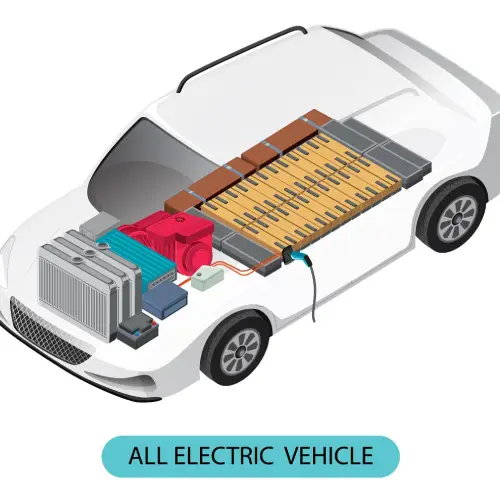
DC-DC Converter: Unlocking the Energy Code of Electric Vehicles Introduction to the DC-DC Converter The onboard DC-DC converter is a crucial component in electric vehicles (EVs). It’s primarily responsible for converting the high-voltage DC power from the battery into the low-voltage DC power needed by various electronic components and control systems within the vehicle. The operation of a DC-DC converter involves multiple modules, including power conversion, driving, and control, ensuring that energy is safely and efficiently transferred. Functions of the DC-DC Converter In electric vehicles, the DC-DC converter plays several key roles. First, it provides the necessary power for systems like power steering, air conditioning, and other auxiliary equipment, ensuring the vehicle operates smoothly. Additionally, since many of the electronic components and control systems in a pure electric vehicle use low-voltage power, the DC-DC converter ensures that the low-voltage battery is sufficiently charged. In some systems, the DC-DC converter even replaces the traditional 12V alternator, becoming the primary power source for recharging the high-voltage battery and supplying the 12V power load. DC-DC Converter Types There are various types of onboard DC-DC converters, including boost, buck, and buck-boost converters, which can be selected and configured based on specific needs. When selecting a converter, factors such as the vehicle’s top speed, acceleration, weight, maximum torque, and power requirements must be considered to ensure the converter’s power capacity meets the vehicle’s needs. Future Trends It’s worth noting that as EV technology continues to evolve, onboard DC-DC converters are also being optimized and upgraded. In the future, with the rise of higher voltage systems and the adoption of 48V systems, DC-DC converters will play an even more critical role in providing stable and efficient power to vehicles. Key Specifications of the Onboard DC-DC Converter The main specifications of onboard DC-DC converters cover several key parameters and characteristics, which not only impact the converter’s performance but also directly affect the stability and reliability of the vehicle’s electrical system. Here’s a detailed look at these key specifications: Output Current Capability: This refers to the maximum output current that the DC-DC converter can provide. This parameter directly determines whether the converter can meet the power demands of the vehicle’s electronic systems. It’s crucial to ensure the converter’s output current capability is robust enough to handle various load conditions. Conversion Efficiency: This indicates how efficiently the DC-DC converter transforms input power into output power. Higher efficiency means less energy loss, which is essential for improving the overall energy efficiency of the vehicle’s electronic systems. Therefore, when choosing a converter, preference should be given to products with high conversion efficiency. Power Rating: The power rating of the DC-DC converter is a critical specification, determining the scale of power the converter can handle. Different vehicle types often have varying power needs, so it’s important to select a converter with a power rating that matches the vehicle’s configuration and actual requirements. Size and Weight: Given the limited space inside electric vehicles, the size and weight of the DC-DC converter are important factors to consider. Smaller and lighter converters help save space and optimize vehicle layout. Thermal Performance: Thermal performance is key to the stability of the DC-DC converter. In high-temperature environments, good thermal performance ensures that the converter operates normally and avoids damage due to overheating. Therefore, the converter’s cooling method and effectiveness should be considered when selecting a unit. Electrical Safety Performance: The electrical safety performance of the DC-DC converter is also critical. This includes compliance with input-output wiring standards, grounding resistance requirements, and specifications for electrical clearance and creepage distance, all of which are necessary to ensure safe operation. Electromagnetic Compatibility (EMC): EMC refers to the DC-DC converter’s ability to operate without exceeding specified electromagnetic interference (EMI) levels, while also being resilient to external interference. This is vital for maintaining the stability and reliability of the vehicle’s electrical system. Reliability: Reliability reflects the DC-DC converter’s stability and durability during long-term operation. A highly reliable converter reduces the likelihood of faults and enhances the overall performance of the vehicle.   Topologies of the Onboard DC-DC Converter The topology of a DC-DC converter is a key factor in its design and performance. The topology determines the path and method of energy conversion, significantly impacting the converter’s efficiency, reliability, and cost. Here are some common topologies of onboard DC-DC converters: Non-Isolated Bidirectional DC-DC: Simple structure with direct component connections and no extra energy loss, leading to high efficiency. High capacitor requirements on the boost side. Main circuit structures include bidirectional half-bridge boost-buck circuits, bidirectional buck-boost circuits, bidirectional buck circuits, and bidirectional Zeta-Sepic circuits. Isolated Bidirectional DC-DC: Adds a high-frequency transformer to the non-isolated design, achieving electrical isolation. The circuit topology on both sides of the high-frequency transformer can be full-bridge, half-bridge, or push-pull types. Utilizes more power switches, offering a broader voltage range and the advantage of electrical isolation. Boost Converter Topology: Used to step up the input voltage to a higher voltage. Basic structure includes an inductor, switch, diode, and output filter capacitor. Buck Converter Topology: Used to step down the input voltage to a lower voltage. Simple structure with high efficiency, commonly used in automotive applications. Buck-Boost Converter Topology: Capable of both stepping up and stepping down the input voltage, suitable for situations where the input voltage varies widely. Can convert input voltage that is greater than, equal to, or less than the output voltage. Flyback Converter Topology: Suitable for low-power, high-voltage applications. Converts voltage through the storage and release of energy in a magnetic field. Half-Bridge Converter Topology: Another topology for converting input voltage to output voltage. Basic structure includes two switches, a pair of diodes, and an output filter capacitor. Brogen’s DC-DC Converter Systems At Brogen, we offer a comprehensive range of DC-DC converters designed to meet diverse needs. Our converters cover power options from 0.6 kW to 6 kW and are available with natural cooling, air cooling, and liquid cooling options. We provide both step-down and step-up configurations, with input voltage ranges from 40 – 700

heavy duty electric truck
Heavy Transport, Industry Insight

18-Ton Heavy-Duty Electric Truck – E-Powertrain Configuration

18-Ton Heavy Duty Electric Truck: E-Powertrain Configuration As electric vehicles continue to rise in popularity, pure electric light trucks and tractors are gaining traction due to their efficiency and cost-effectiveness. However, heavy trucks can also benefit from electrification. This 18-ton heavy duty electric truck features a powerful 322 kWh battery, providing an estimated range of approximately 460 kilometers under consistent driving conditions. This makes it an excellent choice for urban logistics and intercity transportation across various regions. 322 kWh EV Battery System This vehicle is equipped with a liquid-cooled battery systems boasting an impressive capacity of 322 kWh. The battery pack is securely integrated within the chassis frame, offering excellent protection and leaving ample space on both sides for additional installations, such as toolboxes. 160 kW Electric Drive Axle This vehicle is equipped with a two-speed electric drive axle, featuring a drive motor with a peak power of 160 kW and a maximum output torque of 27,600 N·m. The integration of the electric drive axle eliminates the need for components like the driveshaft and universal joints, enhancing overall efficiency and performance. Compact and Lightweight Design For cargo trucks, curb weight has always been a major concern, as it directly affects the vehicle’s loading capacity and consequently, the profitability of each trip. Even though this vehicle is equipped with a large 322 kWh battery system, its curb weight control is still quite impressive. The chassis has an unladen weight of only 7800 kg, with a gross vehicle weight of 18,000 kg. Conclusion Given the current competitive landscape in the logistics industry, businesses and individuals are continually striving to reduce costs and improve operational efficiency. With their outstanding economic performance and efficient transportation capabilities, pure heavy duty electric trucks have become a new choice for urban distribution and intercity transportation. Our Solution for Heavy Duty Electric Trucks At Brogen, our customizable EV systems accelerate heavy-duty electric truck development by reducing R&D costs and time, boosting efficiency, and providing a competitive advantage for EV manufacturers in the rapidly expanding market. Electric Axle 165 kW – 360 kW Explore Traction Battery Customizable Explore Auxiliary Inverter DC/DC, DC/AC, PDU Explore Contact Us Get in touch with us by sending us an email, using the Whatsapp number below, or filling in the form below. We usually reply within 2 business days. Whatsapp: +8619352173376 Email: contact@brogenevsolution.com ContactFill in the form and we will get in touch with you within 2 business days.Please enable JavaScript in your browser to complete this form.Please enable JavaScript in your browser to complete this form. Name * FirstLast Work Email *Company Name *Your EV Project Type *– Please select –BusLight-duty truckHeavy-duty truckConstruction machineryVesselOthers (please write it in the note)Your Interested Solutions *– Please select –MotorBatteryChassise-AxleAuxiliary inverterOBC / DCDC / PDUAir compressorEPS / EHPSBTMSOthers (please write it in the note)Do you have other contact info? (Whatsapp, Wechat, Skype, etc.)Please introduce your EV project and your request here. * Checkbox * I consent to receive updates on products and events from Brogen, and give consent based on Brogen’s Privacy Policy. Submit

lithium forklift battery factory - 3
Industry Insight, Specialty Equipment

How to Choose the Right Electric Forklift Battery: The Complete Guide

How to Choose the Right Electric Forklift Battery: The Complete Guide Introduction For businesses that rely on forklifts, the choice of electric forklift battery can significantly impact overall operational efficiency and, in the long run, influence substantial time and financial costs. By selecting the appropriate forklift battery, forklift manufacturers can ensure the safety and performance of their products in a competitive market. This guide will walk you through the various types of electric forklift batteries, their key differences, price ranges, and how these battery options can affect your business’s daily operations. Quick Access Types of Electric Forklift Batteries​ Electric Forklift Battery Lifespan​ Electric Forklift Battery Maintenance​ Requirements for Forklift Battery Charging Stations​ Safety Comparison​ Price​ How to Determine if Lithium-Ion Batteries are Suitable for Your Forklifts​ How to Choose the Right Electric Forklift Battery​ Brogen’s Electric Forklift Battery Solutions​ Contact Us Types of Electric Forklift Batteries There are two primary battery types powering electric forklifts: lead-acid and lithium-ion. Lead-Acid Batteries As the traditional choice for forklift power, lead-acid batteries utilize a chemical reaction between lead plates and sulfuric acid to generate electricity. These batteries are characterized by their bulky size, liquid electrolyte, and requirement for regular maintenance. Key components include cells, bars, plates of lead dioxide, cables, and electrolytes. The electrochemical reaction between the lead plates and the electrolyte solution allows for the flow of ions, producing an electric current. Lithium-Ion Batteries (Primarily Lithium Iron Phosphate) Introduced in the early 1990s, lithium-ion batteries, particularly Lithium Iron Phosphate (LFP), have gained significant popularity in the material handling industry. These batteries offer higher energy density and a more compact design compared to lead-acid batteries. They are sealed and require minimal maintenance. Lithium-ion batteries operate on the principle of lithium-ion movement between the anode and cathode through an electrolyte. During discharge, lithium ions move from the anode to the cathode, generating electricity. Electric Forklift Battery Lifespan Like any business expense, electric forklift batteries are a cost that needs to be managed over time. The type of battery a forklift uses determines how often the battery needs to be manually replaced. Lead-acid and lithium-ion batteries have different lifespans: Lead-Acid Batteries: 1000 – 1500 cycles Lead-acid batteries have a longer charging time compared to lithium-ion batteries. They are primarily charged using traditional charging methods, typically overnight after a shift, using a low current charge for approximately 8 to 10 hours until fully charged. After a long charging period, the batteries need to cool for 6 to 8 hours before they can be used again.  Traditional charging is mostly done overnight, making it suitable for single-shift operations. This also means that lead-acid batteries typically do not undergo opportunity charging. Doing so can quickly damage the battery, wear it out faster, and reduce the number of cycles. Overall, lead-acid forklift batteries can last 3 to 5 years (or 1000 to 1500 charge cycles) with a normal weekly operation of 40 hours. Lithium-Ion Batteries: 3500 cycles Lithium-ion batteries can be easily charged using opportunity charging because they can be fast-charged. This type of charging involves using a specialized high-current charger to quickly recharge the battery. Opportunity charging can be done as needed or at convenient times, making lithium-ion batteries more efficient. If properly maintained, lithium-ion forklift batteries can last 2000 to 3000 cycles, or approximately 7 to 10 years (assuming 300 working days per year). Electric Forklift Battery Maintenance To ensure that lithium-ion and lead-acid batteries perform at their best, proper maintenance is essential. Without appropriate forklift battery maintenance, their lifespan can be significantly reduced. To maximize lifespan and overall battery capacity, users of both types of batteries should follow certain practices. However, lead-acid batteries require more care and attention compared to lithium-ion batteries. Lead-Acid Forklift Battery Maintenance Requirements Equalization (Battery Balancing): In traditional lead-acid batteries, internal acid, and water can often stratify (separate horizontally, with more concentrated acid near the bottom). This can lead to the formation of sulfate crystals at the bottom of the battery, reducing its ability to hold a charge. Equalization helps break down these crystals, but if the battery is left too long, the crystals may not break. Temperature Control: Lead-acid batteries must be kept within a certain temperature range to avoid shortening their lifespan. They can become very hot during charging, requiring a temperature-controlled space for charging and storage. Typically, using lead-acid batteries requires a significant fixed space to store the batteries. Water Level Management: These batteries need to be checked approximately every 10 charge cycles to ensure they have enough water. “Watering” the battery can be a tedious and time-consuming task for individual batteries. Lithium-ion Batteries Maintenance In comparison, lithium-ion batteries require much less maintenance. They come equipped with a Battery Management System (BMS) that automatically balances the cells, operate well at higher temperatures (making temperature control less of an issue), and do not require any water level management. Requirements for Forklift Battery Charging Stations Lead-Acid Forklift Battery Lead-acid forklift batteries must be completely removed from the forklift and placed onto a separate forklift battery charger. Many of these chargers can perform equalization. If there are many forklifts in operation, multiple chargers are needed, and sufficient space is required for cooling several units after charging.  This process involves employees using specialized lifting equipment to swap out discharged batteries for charged ones regularly. While not physically demanding, this task can be time-consuming and may impact operational efficiency for those looking to optimize productivity.  Additionally, lead-acid batteries require dedicated charging areas with proper ventilation and temperature control. This is because they can become very hot and release harmful fumes during charging. Lithium-ion Battery In contrast, lithium-ion forklift batteries do not require separate charging spaces, cooling, or a fully charged backup battery when another is fully discharged—they can be plugged directly into the charger without needing to be removed from the forklift, making the charging process straightforward with no further actions required. Safety Comparison Safety Risks of Lead-Acid Forklift Batteries Spillage: Lead-acid batteries contain highly toxic sulfuric acid, which can spill, especially since these

axial flux motors for electric motorcycles
Industry Insight, Technologies

Axial Flux Motors for Electric Motorcycles – Benefits & Applications

Axial Flux Motors for Electric Motorcycles – Benefits & Applications As environmental awareness increases and the shift towards sustainable energy continues, the motorcycle industry is rapidly advancing towards electrification, smart technology, and high performance. The demand for electric motorcycles is on the rise, and their market share is expanding significantly. To meet the growing consumer demand for personalized experiences, future motorcycles will focus on enhanced performance, including faster speeds, more stable handling, and improved safety. Our axial flux technology is at the forefront of these trends, significantly boosting the performance of electric motorcycles. This innovative technology provides manufacturers with a crucial competitive advantage in the rapidly growing electric motorcycle market. Explore how our cutting-edge solutions can drive your success in the evolving landscape of electric motorcycles.   Powerful Electric Motorcycle Motors for High-End Models Increase in storage space 0 % Improvement in overall range 0 % 0-50 km/h acceleration 0 s Our e-powertrain for electric motorcycles adopts innovative axial flux motor technology, delivering higher torque and output power while reducing kinetic energy loss and increasing traction efficiency. With the same motor diameter, our axial flux motor‘s power density is 3 times that of a radial flux motor, and its torque density is twice as high. When delivering the same torque and power output, our motor’s volume is reduced by 50%, and its weight is decreased by approximately 50%. Additionally, our motor features a larger cooling surface and superior cooling performance, allowing for prolonged high-output power. Compared to radial flux motors, our motor’s peak power output capability is more than doubled. In continuous operation, our 15 kW electric powertrain matches the power output of a 150 cc fuel motorcycle. It can operate at over 90% efficiency in more than 90% of conditions, resulting in lower energy consumption, better performance, and increased energy recovery. With our axial flux motor, motorcycle range can be improved by over 15%, without changing other components. Moreover, even the 15 kW axial flux electric motor system weighs just 15 kg, significantly lighter than radial flux drive motors. Even with a side-mounted layout, it hardly affects the vehicle’s center of gravity. The side-mounted axial flux motor still allows the electric motorcycle to achieve a lean angle of 40 degrees, comparable to fuel motorcycles. This maintains the vehicle’s performance and range while preserving the joy of riding. 9 Advantages for a Comprehensive Upgrade 30% – increase in battery and storage space 3.2 seconds – acceleration from 0 to 50 km/h 15% – increase in range 9% – increase in drive efficiency Double 90% – motor efficiency MAP 40° – maximum tilt angle 108% – increase in energy recovery IP68 – high waterproof rating Excellent heat dissipation capability Benefits of Axial Flux Motors for Electric Motorcycles Compact Design for More Powerful Performance Compared to the commonly used radial flux motors, axial flux motors offer significant advantages. They can deliver multiple times the power within the same volume and weight or reduce volume and weight by more than 50% at the same power level. This means that electric motorcycles using our axial flux motors not only have significantly more power but are also more conveniently and flexibly arranged. For example, our 15 kW side-mounted electric motorcycle powertrain assembly, with a peak power of 15 kW and an axial dimension of less than 83 mm, is only about 1/3 the size of a radial flux motor of the same power. Better Cornering Ability In practical performance, the application of our axial flux motors allows the electric motorcycle to achieve a maximum lean angle of 40°, comparable to that of traditional fuel-powered motorcycles. The power tuning is highly refined, allowing precise torque output with small throttle adjustments within a turn. This ensures excellent cornering ability, on par with fuel-powered counterparts. Additionally, the acceleration response of the electric drive is faster, providing an enhanced riding experience. Higher Torque for Superior Climbing Ability of Electric Motorcycles Professional testing and analysis reveal that an ordinary household car can handle slopes of around 20°, while 4WD SUVs can manage up to 26°. Only a select few robust 4WD off-road vehicles can conquer slopes as steep as 30°. At a 26° incline, it becomes difficult for a person to maintain balance. However, an electric motorcycle equipped with our axial flux motor can easily perform a “half-hill start” on such slopes, thanks to its powerful 300 N.m wheel-end torque. When climbing hills, off-roading, mountain riding, or commuting, our axial flux motors for electric motorcycles help handle these challenges with ease. Product Portfolio – Motors for Electric Motorcycles Model 6K 9K 15K Bus voltage 72 VDC 72 VDC 72 VDC Ratio 6.095 8.75 7.5 Rated power 3.5 kW 4 kW 6 kW Peak power 6 kW 9 kW 15 kW Assembly rated speed 3200 rpm 4000 rpm 4500 rpm Assembly peak speed 5500 rpm 9500 rpm 11500 rpm Assembly weight 9.2 kg 12 kg 15 kg Maximum efficiency 92% 93% 94% https://youtu.be/UhS63H-T0Z4?si=kjOq7NaKO3JRByeG Frequently-Asked Questions How to purchase these axial flux motors for electric motorcycles? You can purchase these motors from us by filling the form below with your project information and requirements. Our Sales Representative will get in touch with you in 2 business days. Notice: Due to high demand, we are currently only accepting business projects and cannot accommodate personal projects. To assist you better, please include your business information in your inquiry to help us understand your requirements. Do you offer customization services? We offer customization services for your project, but please note that an additional development fee will apply. Do you have other options for axial flux motors? Yes, our axial flux motor systems offer power options from 6 kW to more than 800 kW. Learn more here: https://brogenevsolution.com/axial-flux-motor-technology-for-electric-vehicles/ What’s the price of these motors? The price varies based on your purchase quantities. Therefore, we need more information about your project to provide an accurate quotation. Can I purchase just one motor? Sorry, we don’t accommodate personal projects and have MOQ requirements.  What’s the process of purchasing these

standard battery pack for electric bus / hcv
Industry Insight

How to Design a BEV Traction Battery System? – Overview

Designing Better BEV Traction Battery Systems Brief Introduction Designing a suitable traction battery system for Battery Electric Vehicles (BEVs) is crucial for ensuring optimal performance, safety, and longevity of the vehicle. As BEVs become increasingly popular due to their environmental benefits and efficiency, the demand for advanced battery systems continues to grow. A well-designed traction battery system not only meets the power and range requirements of the vehicle but also addresses critical factors such as safety, cost, and environmental impact. In this blog, we will explore the key aspects of designing a traction battery system, including safety and performance requirements, issues to be addressed, design processes, and the information needed about the vehicle to achieve a perfect design, as well as a detailed case study of designing a battery system. Purpose of the EV Traction Battery System Design To provide a traction battery system with optimal performance based on the design requirements of the entire vehicle. Safety performance requirements Electrical performance requirements Battery selection and system configuration Issues to be Addressed Design structure and process within allowable size and weight to meet the vehicle’s power requirements Find simple and feasible processes Reduce costs Improve technical performance where conditions permit Address and resolve environmental pollution issues EV Traction Battery Design Process Understand vehicle requirements Design system power Design system capacity Thermal design System integration Simulation and validation Parameters to Determine and Issues to Address 1. Electrical Characteristics Nominal voltage and operating voltage range; Nominal capacity and available capacity range; Regular discharge current of the traction battery system; Charging requirements of the traction battery system. 2. Power Characteristics Maximum output power and duration of the traction battery system; Maximum regenerative power and duration of the battery system. 3. Environmental Characteristics Operating temperature range of the traction battery system; Charging temperature range; Storage temperature range. 4. Physical Characteristics Structural and dimensions of the traction battery system; Quality of the traction battery system; Other mechanical performance and protection requirements. 5. BMS Requirements Management and protection functions of the BMS; Determination of battery SOC and SOH; Communication methods and transceiver design requirements; Control requirements and communication protocols. 6. Vehicle Interface Requirements Physical interfaces: battery installation, fixing methods, space orientation of cooling medium, and related pipelines; Electrical interfaces: vehicle harness definition and technical specifications, connector model, and pin definitions; Communication interfaces: communication with the vehicle, internal communication of the BMS, communication with the charger. Information Needed About the Vehicle The more detailed the understanding of the vehicle, the more perfect the traction battery system design will be. Not only the motor and vehicle control strategies but also the vehicle’s mass, dimensions, space, and operating conditions must be thoroughly understood: Vehicle parameters Vehicle motor parameters Required driving range of the vehicle Regenerative power Installation space dimensions of the traction battery system and installation and fixing requirements Quality requirements of the traction battery system Charging methods and interfaces Vehicle operating conditions Operating environment temperature range Charging environment temperature range Power requirements of auxiliary systems Characteristic parameters of the auxiliary battery Traction Battery System Design Steps Determine vehicle design requirements Determine motor requirements Determine power requirements of the traction battery system Determine the voltage range of the traction battery system Determine the type of batteries required for the traction battery system Determine the SOC application range of the traction battery system Determine the effective and actual capacity range of the traction battery system Determine the combined structure of the traction battery system Determine the BMS requirements of the traction battery system Determine the interfaces of the traction battery system Determine other methods such as cooling methods, gas sources, and charging methods Simulation and validation Design optimization Case Study With the following parameters for a BEV, explore how to design a suitable traction battery system to ensure optimal performance, safety, and efficiency. Curb weight: 12600 kg Gross weight: 17150 kg Wheelbase: 5980 mm Frontal area: 7.95 m² Transmission system efficiency: 0.92 Aerodynamic drag coefficient: 0.7 Rolling resistance coefficient: 0.0076+0.000056Vv Required acceleration time: 13 s Required driving range: 200 km (average speed at 40 km/h) Power consumption for electronic accessories and air conditioning: 8 kW Step 1: Determine the vehicle’s power requirements The power balance relationship of an automobile should satisfy: The vehicle power requirement (Pv1) corresponding to the maximum vehicle speed is: The vehicle power requirement (Pv2) corresponding to the maximum climbing grade αm is: The vehicle’s power requirement Pv3 for accelerating from a standstill to a specified acceleration time T is given by the following formula. The required power during full-throttle acceleration is Pv3. The power requirements of the vehicle under different conditions – maximum speed, maximum climbing gradient, and full acceleration – are as follows: 98.7 kW, 91.8 kW, and 65 kW, respectively. Step 2: Determine the system voltage range Based on the selected motor for the vehicle, determine the nominal voltage and voltage application range of the traction battery system. Standards require that the motor and controller safely handle the maximum current within 120% to 75% of the rated voltage. Additionally, the DC bus voltage should not fall below 80% of the motor’s rated voltage. For instance, if the vehicle uses a 384 V motor, the battery system should operate within a voltage range of 300 to 460 V. In this case, a lithium iron phosphate (LiFePO4) battery system with 120 cells connected in series is selected. Step 3: Determine the maximum output power / current of the system Power supply system power requirements: the motor power is 110 kW. Assuming the motor efficiency and controller efficiency are 0.9 and 0.95, respectively, and the power for electronic accessories and air conditioning is 8 kW, the minimum power required by the power supply system is calculated as follows: 110/(0.9×0.95)+8=137 kW Maximum output current: the system’s nominal voltage is 384 V. For high-power output, it’s calculated at 10% below the nominal voltage: Idmax=Pmax/V=137000/(384×0.9)=396 A Duration: the duration should meet the requirements of the entire vehicle, taking into account the SOC requirements (the maximum power demand at 30% SOC). Design redundancy: ensuring a 30%

electric car batteries (1)
Industry Insight

How Long Do Electric Car Batteries Last?

How Long Do Electric Car Batteries Last? The lifespan of electric car batteries is a multifaceted subject influenced by various factors. Here’s a detailed and informative analysis, incorporating relevant figures and information to help you understand how long these batteries typically last. Overview The lifespan of an electric car battery is usually defined not by complete depletion but by the national standard where the battery capacity drops to a specific percentage (e.g. 70%) of its original capacity. Several factors influence the lifespan of EV car batteries, including charging and discharging frequency, depth of discharge, usage duration, environmental conditions, and thermal management. Specific Lifespan for Electric Car Batteries Usage Duration Cycle Life Shelf Life Influencing Factors Electric Car Batteries Maintenance Recommendations Summary The lifespan of these batteries is influenced by various factors. Generally, lithium batteries last between 8 and 10 years, with an effective lifespan of 5 to 7 years. Proper usage and maintenance can extend battery life. Additionally, with ongoing technological advancements, future electric car batteries are expected to have longer lifespans and improved performance. By understanding these factors and following best practices for maintenance, electric car owners can maximize the lifespan and efficiency of their vehicle’s batteries, ensuring reliable performance and cost-effectiveness over time. At Brogen, we provide customizable EV battery solutions. Inquiry: contact@brogenevsolution.com

electric vehiclet traction battery
Industry Insight

What is an Electric Vehicle Traction Battery?

What is an Electric Vehicle Traction Battery? An electric vehicle (EV) traction battery, commonly referred to as an EV battery, is a critical component essential for electric vehicles, electric trains, electric trucks, and other similar applications. It plays a pivotal role in the advancement of new energy vehicles, making a significant stride towards future energy transitions. Below is a comprehensive overview of electric vehicle traction batteries: Definition and Applications Electric vehicle traction batteries serve as energy storage solutions designed specifically to power electric vehicles, electric trains, electric trucks, and comparable electric applications. They distinguish themselves from traditional auxiliary batteries primarily used to ignite combustion engines in automobiles. Types of Electric Vehicle Traction Batteries These batteries encompass a variety of types, including: Structural Composition of an Electric Vehicle Traction Battery Typically, an EV traction battery comprises: Key Features The EV traction batteries offer the following distinct features: Applications These EV batteries find applications across several industries: Conclusion In conclusion, EV traction batteries stand as pivotal components within new energy vehicles, facilitating the transition to sustainable energy practices and environmental conservation. With ongoing technological innovations and expanding market horizons, the future prospects for EV traction batteries appear increasingly promising. At Brogen, we supply EV traction batteries for almost all types of electric vehicles and provide customizable OEM / ODM services. Learn more here: https://brogenevsolution.com/ev-battery/ Inquiry: contact@brogenevsolution.com

electric recirculating ball steering system
Industry Insight, Technologies

Electric Power Recirculating Ball Steering (eRCB) for Commercial Vehicles

Electric Power Recirculating Ball Steering (eRCB) for Commercial Vehicles As the commercial vehicle industry trends towards electrification, intelligent systems, and connectivity, the power steering systems in commercial vehicles are also moving towards electrification. The evolution of commercial vehicle steering technology has progressed through several stages: from mechanical steering, to hydraulic steering, to electro-hydraulic steering, and now to fully electric steering, such as the electric power recirculating ball steering. Our eRCB installed on hybrid electric trucks What is the Electric Power Recirculating Ball Steering (eRCB) System? Unlike traditional mechanical recirculating ball steering systems, the electric power recirculating ball (eRCB) steering system integrates an electric motor and a reduction mechanism at the input end of the mechanical recirculating ball steering gear. This system uses steering signals, vehicle speed signals, and active control commands to control the motor, generating steering torque. This allows for different levels of power assistance and enables active steering functions. How Does the Electric Power Recirculating Ball Steering Work? When the steering wheel is turned, a torque sensor sends a torque signal to the controller. This signal is generated by a torsion bar inside the steering shaft, where the ends of the bar twist relative to each other under external force, reflecting the angle of twist to the torque sensor. The steering torque is directly proportional to the torsion bar’s twist angle. A vehicle speed sensor sends a speed signal (a square wave signal) to the controller. The controller then processes the torque signal and the speed signal from the dashboard and uses a pre-set force model to control the DC motor. By adjusting the current to the motor, the output torque changes, which is amplified by the reduction mechanism to directly assist the steering gear. What Are the Advantages of Electric Power Recirculating Ball Steering Systems? Compared to traditional hydraulic power steering, electric power recirculating ball steering offers the following advantages: 1. Reduced Procurement Costs Traditional hydraulic power steering systems for electric vehicles require an additional electric motor and controller, as there’s no engine-driven hydraulic pump. This setup can cost significantly more than electric steering. 2. Fewer Components and Lighter Weight Hydraulic steering for electric vehicles requires extra components like hoses, reservoirs, pumps, motors, and controllers. In contrast, electric power steering is an integrated system that saves time and effort during assembly. It’s approximately 50% lighter than hydraulic steering, making it easier to install and maintain, while also enhancing vehicle layout and safety. 3. Extended Driving Range by 25% Hydraulic steering systems need a motor with at least 2 kW power that runs continuously. In contrast, electric steering only requires a 12V (or 24V) power source, with a bus only needing around a 400W motor. The system only consumes power when steering, leading to minimal energy loss. Tests show that this can extend the driving range by over 25%. 4. Improved Steering Ease and Stability The eRCB system adjusts the steering assistance based on vehicle speed—light and easy steering at low speeds and stable, secure handling at high speeds, improving vehicle stability and control. 5. No Hydraulic Fluid, No Leaks Since the eRCB system doesn’t use hydraulic fluid, it eliminates the risk of leaks and reduces environmental pollution. 6. High Reliability and Maintenance-Free The eRCB system is highly reliable, maintenance-free, and performs well even in low temperatures. 7. Broad Applicability The eRCB system is versatile, suitable for fuel-powered vehicles, and hybrid vehicles, and is the ideal choice for pure electric vehicles. Brogen’s eRCB Solutions System Functions Speed-sensitive power assistance Active return Dampling compensation function Friction compensation function Rack end protection function Inertia compensation function Temperature management Motor thermal protection System Advantages Provides eRCB products supporting L2 autonomous driving Configurable interfaces, compatible with various TAS sensor types Supports CAN/CANFD interface Supports Cybersecutiry hardware encryption Supports OTA upgrades Download Brochure Contact Us Get in touch with us by sending us an email, using the Whatsapp number below, or filling in the form below. We usually reply within 2 business days. Email: contact@brogenevsolution.com Respond within 1 business day Whatsapp: +8619352173376 Business hours: 9 am to 6 pm, GMT+8, Mon. to Fri. LinkedIn channel Follow us for regular updates > YouTube channel Ev systems introduction & industry insights > ContactFill in the form and we will get in touch with you within 2 business days.Please enable JavaScript in your browser to complete this form.Please enable JavaScript in your browser to complete this form. Name * FirstLast Work Email *Company Name *Your Project Type *– Please select –Car, SUV, MPVBus, coach, trainLCV (pickup truck, light-duty truck, etc.)HCV (heavy-duty truck, tractor, trailer, concrete mixer, etc.)Construction machinery (excavator, forklift, crane, bulldozer, loader, etc.)Vessel, boat, ship, yacht, etc.Others (please write it in the note)Your Interested Solutions *– Please select –Motore-AxleBatteryChassisAuxiliary inverterOBC / DCDC / PDUAir brake compressorEPS / EHPS / SbW / eRCBBTMSOthers (please write it in the note)Do you have other contact info? (Whatsapp, Wechat, Skype, etc.)Please introduce your project and your request here. * Checkbox * I consent to receive updates on products and events from Brogen, and give consent based on Brogen’s Privacy Policy. Submit

electric dump truck ev
Heavy Transport, Industry Insight, Light Commercial Vehicles

EV Truck Drive Systems: Direct Drive Motor vs. E-Axle

When it comes to the pure EV truck, understanding the differences between traditional electric motor structures and modern e-axle systems is crucial. Let’s use an electric dump truck as an example to explore these differences. Traditional Drivetrain Structure – Direct Drive Motor The traditional drivetrain in electric trucks closely resembles the layout found in conventional vehicles. The drive motor, equivalent to a diesel engine, is the heart of this system. Directly behind the motor is a reducer, functioning similarly to a traditional gearbox. The reducer’s job is to increase torque by reducing the motor’s speed, effectively amplifying power. This amplified power is then transmitted through a driveshaft to the rear axle. The rear axle, with a gear ratio of approximately 5.857, is comparable to that of traditional dump trucks. How It Works A notable feature of this system is the two-speed function of the reducer, which allows the vehicle to switch between different gear ratios based on the load, similar to shifting gears in a traditional transmission. This functionality provides both speed and power as needed. E-Axle System Now, let’s delve into the e-axle system. An e-axle integrates the electric motor with the rear axle, combining four major functions: the motor, rear axle, transmission, and differential. This integration brings several significant advantages: However, the e-axle system does present challenges. Integrating the motor with the rear axle reduces space for torque amplification mechanisms, potentially limiting the power output compared to traditional setups with a gearbox. Achieving high power levels with an e-axle requires advanced design and engineering capabilities. Brogen’s Solutions At Brogen, we supply traditional drive motor and e-axle systems for electric vehicle builders. Our e-axle for heavy-duty trucks can deliver a maximum output torque of 50,000 Nm, providing ample power for these vehicles. Our electric motors offer power options ranging from 165 kW to nearly 800 kW, catering to various commercial vehicles, including light trucks, tractors, concrete mixers, and more. Explore our cutting-edge electric axle solutions and see how Brogen can help you achieve success in the rapidly expanding e-mobility sector. Contact

blade battery for battery electric truck
Heavy Transport, Industry Insight, Light Commercial Vehicles, Technologies

How Blade Battery Packs Benefit the Electric Truck?

Electric Trucks Equipped With Blade Batteries: Higher Energy, Lower Consumption The latest all-electric truck from BYD features blade battery packs. Introduced by BYD four years ago, these LFP blade battery packs eliminate the module design, reducing many structural components. The close connection between the upper and lower casings and the battery cells significantly increases volumetric energy density, reaching levels comparable to high-energy-density ternary lithium batteries. This battery electric vehicle model boasts a battery capacity of 94.3 kWh, providing a pure electric range of over 275 kilometers, surpassing the typical 100~200 kilometer range of industry-standard electric light trucks. In addition to the impressive energy density, blade battery technology offers higher thermal stability, lower thermal runaway temperature, smaller thermal runaway reactions, and a reduced likelihood of thermal runaway compared to ternary lithium and standard LFP batteries. This makes the light-duty truck, which operates over longer distances annually, safer. The blade battery’s exceptional thermal management extends battery life, improves charging and discharging efficiency, and shortens charging time. This all-electric truck can achieve over 100 kilometers of range with just half an hour of charging, further enhancing operational efficiency. Electric Truck Chassis Optimization: Better Layout, Higher Load Capacity Unlike traditional electric light trucks that position the standard battery boxes on the sides of the chassis or hang them in the middle, this electric truck’s blade battery is semi-embedded within the chassis frame. This structure integrates the battery into the chassis, making it part of the vehicle’s framework, providing both an energy source and structural rigidity. This design completely revolutionizes traditional electric light truck chassis layouts. Additionally, the semi-embedded design increases the chassis’ ground clearance, improving overall vehicle possibility. The flat-laying design of the chassis battery allows the truck to use a direct-drive system with an integrated electric drive axle. This system features a flat-wire motor and reducer within a shared casing, improving slot fill rate and efficiency. The lightweight aluminum alloy casing enhances transmission efficiency and reduces energy loss compared to traditional direct-drive systems. In terms of the suspension design, the vehicle uses a 3/5+6 leaf spring, with significantly more leaves in the rear axle springs, directly boosting the vehicle’s load capacity. Cabin Design: More Space, Lower Wind Resistance Building on the previous generation electric light truck, which positioned the integrated controller and battery systems on the sides of the chassis under the body, this EV truck continues this design, thanks to the more compact blade battery pack. This allows for a more spacious cabin layout. The cabin details have been optimized, upgrading the traditional mechanical handbrake to an electronic handbrake for increased comfort during driver rest periods while charging. Additionally, the vehicle’s battery system is split into two sets: one located on the side of the chassis under the body, and the other under the tilting cab, powering the low-voltage system of the cabin. This separated design enhances the stability and safety of the cabin’s power supply system. Summary In summary, the new electric light-duty truck, equipped with a 94.3 kWh blade battery, not only significantly improves vehicle range but also addresses user-identified issues through comprehensive upgrades to the chassis structure and cabin design. By leveraging blade battery technology, the vehicle reduces costs and increases efficiency for users. With competitive blade battery prices and enhanced electric truck battery capacity, BYD’s approach to batteries for electric vehicles sets a new standard in the industry. Looking for an EV Battery System for Your Project? Here at Brogen, we provide customized EV battery solutions, including standard LFP battery packs and advanced LFP blade battery systems for trucks, buses, vans, and other construction equipment or specialty vehicles. Contact us through the form below and we’ll get back to you shortly to discuss how we can empower your EV project!

Scroll to Top