Oil-Free Air Brake Compressors For Commercial EVs
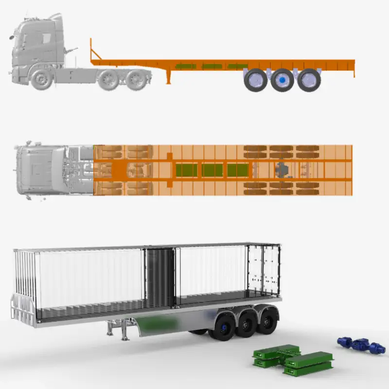
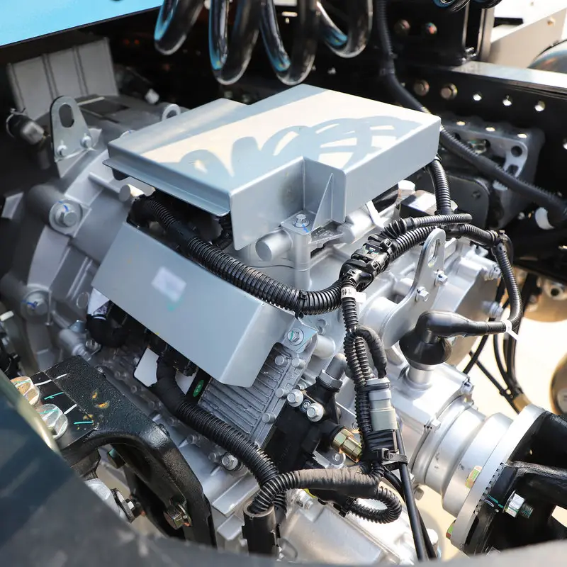
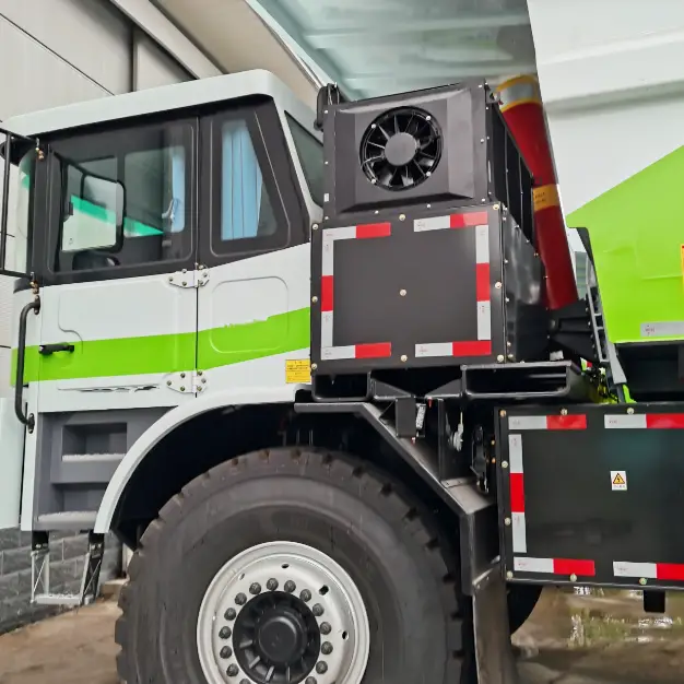
Oil-Free Air Brake Compressor for Commercial EVs: The Next Step in Clean Mobility With the rapid growth of electric vehicles worldwide, the electrification of commercial vehicles has entered a stage of fast expansion. Among their key subsystems, the electric air brake compressor plays a critical role in the pneumatic braking system, air suspension, and other auxiliary air systems. It’s a core component that directly impacts vehicle safety, reliability, and efficiency – and is now entering a rapid phase of technological evolution. This article explores the current market landscape and development trends of EV air brake compressors, particularly for commercial vehicles. 1. What is An Electric Air Brake Compressor in Commercial Vehicles In traditional commercial vehicles, the air compressor is typically driven by the engine. However, in electric vehicles, which no longer rely on internal combustion, an electric air compressor replaces this function. It provides compressed air for the vehicle’s brake system, air suspension, and auxiliary actuators, making it an essential element of EV safety and performance. With strong government policies promoting EVs globally, the market demand for electric air brake compressors has grown significantly. Traditional air compressor Electric air brake compressor 2. Current Status of Electric Air Brake Compressor Technology The shift toward electrification in commercial vehicles has given rise to multiple types of electric air brake compressors, such as screw, vane, and scroll compressors. However, over nearly a decade of market validation, these designs have shown limitations such as oil-gas emulsification, low discharge pressure, and poor reliability – leading to their gradual replacement. Today, piston-type air compressors have become the mainstream solution for electric commercial vehicles, offering better efficiency, reliability, and adaptability to high-pressure systems. Screw compressor Vane compressor Scroll compressor Piston compressor Item Oil-lubricated piston type Screw type Vane type Scroll type Lubricating oil type Traditional diesel engine oil Special screw compressor oil Special vane compressor oil – Driving safety Safe If maintenance is not timely, it will contaminate the air system, causing rubber parts to expand and age, easily leading to brake system failure – Lubricant consumption Small Large Large – Lubricant emulsification and deterioration None Easy Easy – Environmental adaptability (air contact) Less contact with external air Easily affected by external air contamination – Oil-gas separator Not required Required Required – Oil separator filter element lifespan – Short Short – Lubricant temperature control Not required Required Required – Impact of ambient humidity Small Large Large – Discharge pressure Can withstand short-term overload General General Low Special maintenance experience requirements None High High Very high Environmental adaptability Good Poor Poor Poor Service life Good Poor Poor Poor 3. The Rise of Oil-Free Piston Electric Air Brake Compressor Most piston-type electric air compressors in use today are still oil-lubricated, which requires regular oil changes and maintenance. Problems such as oil leakage or contamination can lead to secondary pollution and increased maintenance costs. In constrast, oil-free air brake compressors eliminate the need for lubrication oil, reduce system complexity, and ensure clean, oil-free compressed air – protecting pneumatic components and improving environmental sustainability. Based on years of market application and customer feedback, the trend is clear: oil-free piston compressors are becoming the future direction of EV air brake compressor technology. Oil electric air brake compressor Oil-free electric air brake compressor 4. Oil-Free Air Brake Compressor Technology Overview Among current oil-free air compressor designs, scroll compressors have seen early adoption in electric vehicles. They offer compact structure, smooth operation, and high efficiency. However, due to their tight sealing gaps, scroll compressors require extremely clean intake air, making them vulnerable to dust and humidity, especially since compressors in commercial EVs are often mounted on the chassis. Additionally, scroll compressors tend to have high discharge temperatures and struggle to meet the >1 MPa high-pressure requirements of commercial brake systems. Maintenance is also costly, as damaged scroll plates must be replaced entirely. As a result, oil-free piston compressors have emerged as the mainstream solution due to their superior pressure performance, environmental adaptability, and long service life. Comparison of Oil-Free Air Compressor Types Item Oil-free piston air compressor Oil-free scroll air compressor Discharge pressure Strong high-pressure capability; easily meets the standard requirement of ≥ 1 Mpa. Limited by the scroll sealing structure, poor high-pressure sealing performance leads to low discharge pressure. High-pressure performance decays significantly over time, making it difficult to maintain 1 MPa for long periods. Structural sealing Use a direct-drive motor design with a simple and reliable transmission structure; minimal high-pressure attenuation. Requires a precise clearance between moving components to achieve sealing, resulting in high requirements for sealing materials. The complex sealing structure is prone to thermal deformation and leakage. Environmental adaptability Excellent adaptability; IP67 or higher protection level allows operation in harsh environments (high temperature, low temperature, high altitude). Both the orbiting and fixed scroll plates feature curved surfaces requiring high machining accuracy. The strict sealing demands on upper and lower end faces make it sensitive to environmental conditions. Cooling performance The compressor head uses air or water cooling with an additional cooler, providing excellent heat dissipation. The internal working chamber cannot be externally cooled, making heat removal difficult. Localized overheating occurs easily, resulting in high discharge temperatures. Maintenance Requires no special maintenance – only periodic air filter cleaning. High sealing precision requirements lead to faster seal wear. Maintenance involves disassembling the entire unit to replace seals, making servicing difficult and costly. If scroll plates are damaged, the entire assembly must be replaced. Service life High reliability and long service life. Due to its unique sealing structure, service life is highly dependent on working conditions. Components operate under high temperature, humidity, and pressure, significantly shortening lifespan and overall reliability. 5. Advantages of the Two-Stage Oil-Free Piston Air Brake Compressor In response to the GB 7258 national standard requiring brake air pressure above 1 MPa, and OEMs demanding even higher efficiency and emission reduction, two-stage oil-free piston compressors have become the latest evolution trend. They are designed for high discharge pressure, low exhaust temperature, high efficiency, and long service life. Single-stage oil-free