HVIL Explained: What It Is and Why It's Critical for High-Voltage Safety
With the rapid development of electric vehicles (EVs), especially the increasing demand for fast charging, the operating voltages used in EVs are steadily rising. While some models still use a 200 V platform, the mainstream adopts 400 V systems, and high-end vehicles are increasingly equipped with 800 V architectures. Some OEMs are now developing even higher voltage platforms of 900 V to 1000 V to support ultra-fast 6C charging.
As voltage levels increase, concerns about high-voltage safety in EVs grow accordingly.
1. Safety Challenges Associated with High Voltage
The primary safety risk associated with high voltage is electric shock, particularly when high-voltage components become exposed. Besides shock hazards, two other major safety issues related to high-voltage operation are switch arcing and high-voltage power loss.
1.1 High Voltage Exposure
The generally accepted safety thresholds for human exposure are approximately 50 VAC or 120 VDC. However, actual safety depends heavily on the environment, contact duration, and body resistance. For example, voltages below 36 VAC or 60 VDC are considered relatively safe in dry conditions, but in wet or conductive environments, safe voltages drop to 12 V to 24 V.
Mainstream EV high-voltage systems operate around 400 VDC, far exceeding these safety levels. Exposure to such voltages presents serious risks. To mitigate this, all high-voltage components are enclosed in insulated protective covers. These protective covers must remain securely closed during vehicle operation; any unauthorized opening must be detected and addressed immediately.
1.2 Switch Arcing
High-voltage switches, such as connectors, can generate electric arcs when opened or closed under load. This occurs because when the voltage exceeds the breakdown voltage of the surrounding gas or insulation medium, electrons accelerate and ionize surrounding particles, causing an avalanche effect that sustains an electric arc. Such arcs can severely damage switch contacts and pose fire hazards to nearby components and personnel.
1.3 High-Voltage Power Cutoff
In traditional vehicles, power is provided by an internal combustion engine. When the engine encounters issues – such as high coolant temperature, emission faults, or operational failures – early warnings and appropriate handling are required. In electric vehicles, propulsion is driven by high-voltage electricity from the power battery to the motor. If high-voltage power is suddenly cut off while the vehicle is in motion, it can result in a complete loss of power, posing safety risks to both the vehicle and its occupants. Therefore, early warnings and safety mechanisms must be in place.
Issues such as high-voltage exposure, switching arcs, and unexpected high-voltage disconnection must be detected, monitored, and handled effectively to prevent related safety incidents. The High-Voltage Interlock Loop (HVIL) is a safety mechanism capable of addressing all of these concerns simultaneously.
2. Basic Concept of HVIL
HVIL stands for High Voltage Interlock Loop – a safety system designed to monitor the integrity of the high-voltage circuit using a low-voltage signal loop. It continuously checks the connection status of all high-voltage components and wiring harnesses, ensuring the entire system remains intact and safe.
HVIL systems typically cover critical components such as the battery pack, Battery Management System (BMS), Vehicle Control Unit (VCU), Power Distribution Unit (PDU), Motor Control Unit (MCU), DC/DC converter, PTC heater, wiring harnesses, connectors, and protective covers.
When a fault or disconnection occurs anywhere in the HVIL loop, the system triggers alarms and initiates safety measures.
3. How HVIL Works
3.1 Mechanical Structure
As previously mentioned, switch arcing is a common issue in high-voltage systems during operation. In electric vehicles, the primary switches that require connection and disconnection are high-voltage connectors, namely, plugs and sockets. If these connectors are plugged or unplugged while live, arcing can easily occur. This problem is addressed through specialized mechanical design.
Standard connectors typically have only two terminals: one for the high-voltage positive and one for the negative. HVIL connectors, however, include an additional pair of low-voltage terminals – positive and negative – used by the HVIL system to monitor circuit integrity. These are referred to as HVIL pins.
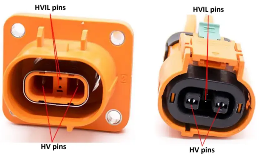
As shown in the diagram above, the HVIL connector features four terminals, with two additional HVIL pins located in the center. The illustration on the right further shows that the contact points of the central HVIL pins are not on the same plane as those of the HV pins on either side. The HVIL pins are shorter, which means that during connection, the HV pins make contact first, followed by the HVIL pins.
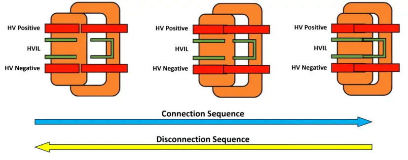
The connection process proceeds from left to right:
- In the left image, all four pins are fully disconnected.
- In the middle image, the two HV pins on either side make contact first, while the central HVIL pins are not yet connected.
- In the right image, the HVIL pins complete the connection, finalizing the engagement of all four terminals.
If the HVIL pins detect an abnormal condition, the high-voltage circuit is immediately interrupted. When the HVIL pins are not connected, the system is in an open-loop state – considered abnormal – and the internal circuit will cut off the high-voltage supply. Therefore, before the HVIL pins engage, the high-voltage circuit remains open, preventing any voltage presence and eliminating the risk of arcing. This design ensures safety during connector engagement.
The disconnection process occurs in reverse order, from right to left: the HVIL pins disconnect first, followed by the HV pins. Once the HVIL pins open the circuit, the high-voltage power is immediately cut off, ensuring that when the HV pins are separated, no voltage is present – thus guaranteeing safe disconnection.
3.2 Electrical Principle
While the issue of switch arcing can be addressed through specialized mechanical design, verifying the integrity of the high-voltage circuit requires an electrical solution.
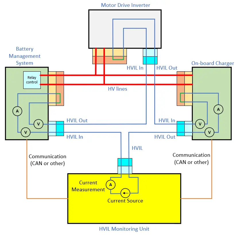
The diagram above illustrates a sample HVIL system, which uses a dedicated HVIL monitoring unit. This unit is connected in series with the HVIL pins of the BMs, MDI, and OBC modules, forming a closed monitoring loop. The HVIL monitoring unit contains a current source that generates a small current. This current flows from the HVIL control unit through the connectors and internal circuits of the BMS, MDI, and OBC, then returns to the control unit.
Under normal conditions, the predefined output current from the HVIL unit should closely match the returning current. If there is any loose, poor, or disconnected connection within the look, the returning current will deviate from the expected value. By comparing the output current (predefined) with the input current (actual return), the HVIL unit can determine the connection status of the system’s connectors:
- If the current matches, all connectors are securely connected.
- If the current decreases, it indicates poor contact or a loose connection, resulting in increased contact resistance.
- If the current drops to zero, it means a connector has been fully disconnected.
While the example uses a current source, the same principle applies with a voltage source. By measuring voltage at different points in the circuit (input, output, and intermediate nodes), the system can also identify abnormal loop conditions.
Once an issue is detected in the main HVIL loop, the next challenge is pinpointing exactly which module or connector is at fault. This requires each module to have internal HVIL monitoring capabilities, specifically the ability to measure key HVIL parameters – namely current and voltage.
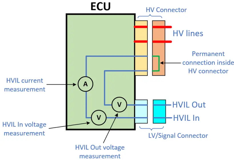
For example, the BMS in the system diagram also has internal HVIL diagnostic capability. It first checks the HVIL current. If the measured current does not match the predefined value, the BMS will further measure the voltage at both ends of the HVIL circuit – namely, “HVIL In” and “HVIL Out”;
- If both “HVIL In” and “HVIL Out” voltages are 0 V, it indicates that current is not entering the BMS at all. This suggests a fault on the input side – such as an unconnected “HVIL In” pin or a related component failure.
- If both “HVIL In” and “HVIL Out” voltages are greater than 0 V, it means that current has successfully passed through the BMS’s internal circuit. The input and internal paths are functioning properly, indicating a fault on the output side – such as a loose or poorly connected “HVIL Out” pin.
- If the “HVIL In” voltage is greater than 0 V but the “HVIL Out” voltage is 0 V, it means that the current cannot exit through the BMS, implying an internal fault within the BMS itself.
It’s important to note that when a fault occurs in the HVIL loop, the current or voltage values may not always drop to zero. Therefore, a threshold must be defined. Faults may not be caused solely by open circuits – issues like poor contact (e.g., a partially dislodged terminal pin) can also significantly increase contact resistance, potentially changing from several milliohms to tens of ohms, while the circuit remains electrically connected.
3.3 Detection Circuitry
In HVIL systems, there are two main types of detection circuits: the DC source method and the PWM-based method.
- DC Source Method:
This approach injects a constant DC voltage signal (VCC) into the HVIL loop to monitor its integrity. As the voltage propagates through the circuit, different points along the loop – such as both ends of an HVIL connector – will exhibit measurable voltages, typically denoted as V1 and V2. By comparing these voltage values, the system can diagnose the connection status of the high-voltage connector.
Advantages: The DC method features a simple circuit design and low implementation cost.
Disadvantages: It’s more susceptible to electromagnetic interference (EMI) and lacks the ability to provide frequency-domain information for more detailed diagnostics.
- PWM-Based Method:
Like the DC method, this approach also measures V1 and V2, but it introduces a controllable switch – such as a MOSFET – to inject a periodic PWM signal into the low-voltage HVIL circuit. By monitoring the returned PWM waveform, the system can determine whether the HVIL loop is intact. If the waveform is distorted or interrupted, a fault in the HVIL loop is indicated.
PWM detection circuits are more complex and versatile. For example, the circuit may use varying control points, add voltage dividers, or adjust resistance values across different parts of the circuit. PWM signals can alter the source voltage or the resistance in the path to enable more granular diagnostics.
Advantages: High immunity to noise, making it suitable for noisy environments common in electric vehicles; improved diagnostic capability through pulse width variation, enabling flexible signal transmission and supporting diverse interlock conditions.
In addition to detecting normal operation or open-loop faults, PWM systems can also identify short circuits to power or shorts to ground within the HVIL loop, offering broader and more reliable fault detection.
4. Handling Strategies
4.1 Response Time
When connecting or disconnecting a high-voltage connector, there is a time delay (Δt) between the contact of the HV terminals and the HVIL terminals.
- During insertion, the HV terminals make contact first, followed shortly by the HVIL terminals. This delay is referred to as Δt1.
- During disconnection, the HVIL terminals break contact first, followed by the HV terminals. This delay is known as Δt2.
This timing difference ensures that:
- The HV terminals are not energized until a secure physical connection is established.
- The system can detect disconnection early and cut off power in advance to prevent arcing or unsafe conditions.
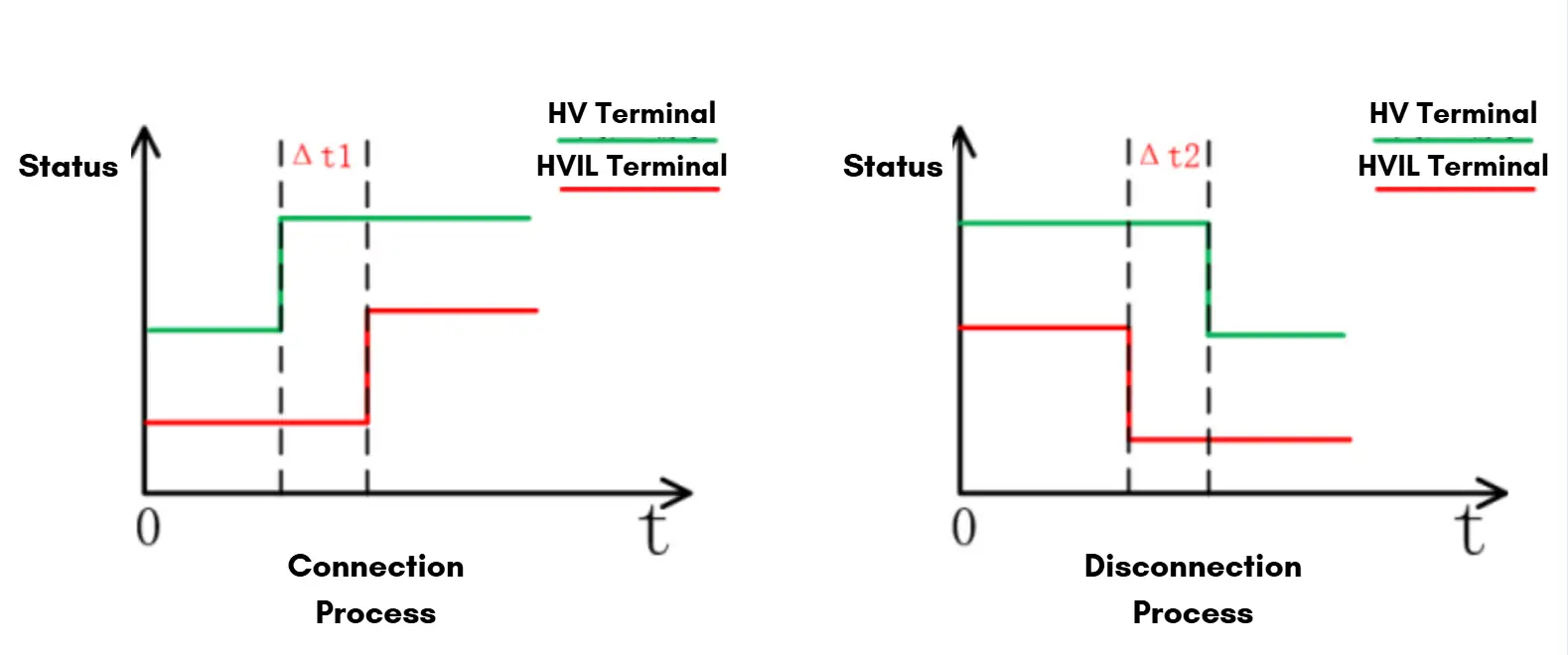
Δt1 and Δt2 are affected by how fast the connector is inserted or removed. Typically, Δt1 is around 1 second, while Δt2 is shorter – about 100 milliseconds – since disconnection happens more quickly.
To ensure safety, the HVIL system must respond faster than Δt2, meaning its detection and shutdown mechanism should activate within 10 to 100 milliseconds to effectively isolate the high-voltage circuit and prevent potential hazards.
4.2 Interlock Levels
The diagram below illustrates a HVIL system with two separate interlock loops: HVIL Loop 1 and HVIL Loop 2.
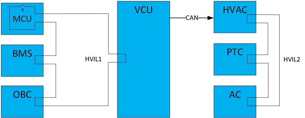
- HVIL Loop 1 starts from the VCU, passes through the MCU, BMS, and OBC, then returns to the VCU.
- HVIL Loop 2 is associated with the HVAC system. It functions as a sub-loop and communicates its status to the VCU via the CAN bus.
In HVIL Loop 1, the MCU includes a protective switch K, which is physically linked to the protective cover of the high-voltage components. As mentioned earlier, high-voltage exposure is a critical safety concern. To mitigate this, insulation covers are installed over high-voltage equipment. These covers often use a lever of push-button mechanism and serve as a physical switch:
- When the cover is opened, the switch is disconnected, triggering the HVIL circuit to open and the high-voltage power supply to shut off.
- When the cover is closed, the switch reconnects, allowing normal operation.
This setup enables lid-open detection and directly addresses high-voltage exposure risks.
HVIL faults can be categorized into three levels, each requiring different safety responses:
- Level 1 – Critical Components: Applies to core high-voltage systems such as BMS, RESS, and OBC. A fault in any of these components poses serious safety risks and may cause complete failure of the high-voltage system. In such cases, immediate shutdown of the high-voltage power supply is typically required.
- Level 2 – Powertrain Components: Includes MCU and motor. If a Level 2 component experiences an HVIL fault, the vehicle may issue a warning and gradually reduce motor power output, allowing the vehicle to decelerate safely and pull over without abrupt loss of propulsion.
- Level 3 – Auxiliary Components: Includes EACP, PTC heater, and DC/DC converter. These components have minimal impact on core driving performance. In the event of an HVIL fault, the system usually issues a warning and may limit or disable the affected component to preserve functionality of more critical systems.
5. Summary
HVIL combines specialized mechanical design, electrical integrity monitoring, and intelligent control to ensure the safety of EV high-voltage systems. It prevents dangerous arcing during connector handling, continuously verifies circuit integrity via current, voltage, or PWM signals, and triggers early warnings and safety measures based on fault severity.
About Brogen
At Brogen, we provide advanced EV solutions for global commercial vehicle manufacturers, enabling them to streamline research and development while capitalizing on cutting-edge technology. Our offerings ensure superior efficiency, extended range, and seamless system integration with proven reliability—empowering our partners to lead in the rapidly evolving green mobility landscape.
Currently, our EV solutions for battery electric heavy trucks have been adopted by vehicle manufacturers in countries and regions such as Canada, Türkiye, Brazil, the Philippines, Indonesia, the Middle East, and more.
- Discover our HCV electrification solution here: https://brogenevsolution.com/heavy-duty-vehicle-electrification-solutions/
- Discover our Public Transport Electrification solution here: https://brogenevsolution.com/public-transport-electrification-solutions/
- Looking for an EV solution for your project? Reach out to us at contact@brogenevsolution.com
Contact Us
Get in touch with us by sending us an email, using the Whatsapp number below, or filling in the form below. We usually reply within 2 business days.
Email: contact@brogenevsolution.com
Respond within 1 business day
Whatsapp: +8619352173376
Business hours: 9 am to 6 pm, GMT+8, Mon. to Fri.
LinkedIn channel
Follow us for regular updates >
YouTube channel
Ev systems introduction & industry insights >