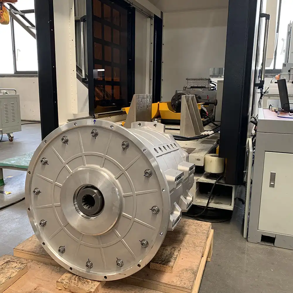
Author name: brogenevsolution.com

DC_DC for hybrid excavator dc-dc converter
EV Industry

DC-DC Converter in EVs: Role, Architecture, and Operating Principles

DC-DC Converter in EVs: Role, Architecture, and Opearting Principles 1. The Role of a DC-DC Converter In simple terms, a DC-DC converter in an electric vehicle (EV) is a step-down voltage converter. Its primary function is to convert the high-voltage DC power from the traction battery into the low-voltage DC power required by the vehicle’s auxiliary electrical system. Conventional internal combustion engine (ICE) vehicles: Powered by an alternator and a 12V lead-acid battery, which supply electricity to components such as headlights, infotainment systems, the ECU, power windows, door locks, and wipers. Electric vehicles: Since there is no engine, there is no alternator. Instead, EVs rely on a high-voltage traction battery (typically 200V-800V) for propulsion. However, most onboard systems – such as the instrument cluster, lighting, infotainment, controllers, and window motors – still operate on a traditional 12V low-voltage system. Without a conversion path, energy cannot flow between the high-voltage and low-voltage domains. The DC-DC converter bridges this gap. It replaces the alternator in ICE vehicles and acts as the core low-voltage power supply in EVs. 2. Circuit Composition of a DC-DC Converter Most EVs use isolated LLC resonant DC-DC converters, either unidirectional or bidirectional. While sophisticated in design, their operating principle is similar to that of a common switch-mode power supply. A typical DC-DC converter consists of the following components: 2.1 Main Power Circuit Input EMI filer: Smooths the high-voltage DC from the traction battery, reducing voltage ripple and electromagnetic interference. Power switching stage: Typically a half-bridge or full-bridge structure. Controlled by high-frequency switches (MOSFETs/IGBTs), the DC input is inverted into a high-frequency AC square-wave signal. This is the core of energy conversion. High-frequency transformer: Electrical isolation: Provides galvanic isolation between high-voltage and low-voltage sides for safety and noise immunity. Voltage transformation: Achieves step-down conversion according to the winding ratio. Output rectifier: Converts the transformer’s secondary high-frequency AC into DC. Typically implemented with diodes or synchronous rectification MOSFETs. Output filter: A combination of inductors L and capacitors C smooths the rectified DC to provide a stable 12V output. 2.2 Control and Drive Circuit Main control unit: The “brain” of the DC-DC converter. It continuously monitors voltage and current, compares them with reference values, and generates PWM signals to adjust the duty cycle of the switching devices for precise voltage regulation. Driver circuit: Amplifies the PWM signals from the control unit to ensure the power switches operate rapidly and efficiently. Sampling and protection circuit: Continuously monitors input voltage, output voltage, output current, and temperature. In case of over-voltage, under-voltage, over-current, over-temperature, or short-circuit conditions, the controller immediately shuts down PWM input to protect both the converter and the low-voltage system. 3. Operating Principle of a DC-DC Converter The working process can be summarized in four stages: DC → High-Frequency AC → Transformation → DC. Inversion (DC-AC): The control unit generates four PWM signals to alternately drive the switches in the full-bridge circuit (Q1-Q4). This converts the high-voltage DC (e.g., 400V) into a high-frequency AC square wave, typically in the kHz range. Transformation & Isolation: The AC signal passes through the LLC resonant tank, enabling zero-voltage switching (ZVS) of MOSFETs, which minimizes switching losses and improves efficiency. The high-frequency transformer then steps down the voltage and provides galvanic isolation. Rectification (AC-DC): The transformer’s secondary AC output is rectified by the output stage, often using synchronous rectification with MOSFETs to reduce conduction losses compared to diodes. Filtering & Output: The rectified pulsating DC passes through an LC filter to produce a stable 12V DC supply for onboard low-voltage devices. Closed-Loop Feedback Control: The control chip continuously monitors the output voltage via sampling resistors. If the load increases (e.g., headlights and AC operating simultaneously) and the voltage drops, the controller increases the PWM duty cycle to deliver more energy to the low-voltage side, restoring the output to 12V. If the load decreases, the duty cycle is reduced. This negative feedback loop ensures that the DC-DC converter maintains an extremely stable 12V supply regardless of load variations. Our DC-DC Converter Solutions At Brogen, we provide a full range of DC-DC converter solutions for electric vehicles, covering power outputs from 0.6 kW to 6 kW, with options for natural, air, or water cooling. Our portfolio also includes OBC & DC-DC combo units, as well as 3-in-1 CDU combo units that integrate the OBC, DC-DC, and PDU into a single compact system. Learn more here: https://brogenevsolution.com/obc-dcdc-pdu/ Looking for an EV solution for your project? Reach out to us at contact@brogenevsolution.com Contact Us Get in touch with us by sending us an email, using the Whatsapp number below, or filling in the form below. We usually reply within 2 business days. Email: contact@brogenevsolution.com Respond within 1 business day Whatsapp: +8619352173376 Business hours: 9 am to 6 pm, GMT+8, Mon. to Fri. LinkedIn channel Follow us for regular updates > YouTube channel Ev systems introduction & industry insights > ContactFill in the form and we will get in touch with you within 2 business days.Please enable JavaScript in your browser to complete this form.Please enable JavaScript in your browser to complete this form. Name * FirstLast Work Email *Company Name *Your Project Type *– Please select –Car, SUV, MPVBus, coach, trainLCV (pickup truck, light-duty truck, etc.)HCV (heavy-duty truck, tractor, trailer, concrete mixer, etc.)Construction machinery (excavator, forklift, crane, bulldozer, loader, etc.)Vessel, boat, ship, yacht, etc.Others (please write it in the note)Your Interested Solutions *– Please select –Motore-AxleBatteryChassisAuxiliary inverterOBC / DCDC / PDUAir brake compressorEPS / EHPS / SbW / eRCBBTMSOthers (please write it in the note)Do you have other contact info? (Whatsapp, Wechat, Skype, etc.)Please introduce your project and your request here. * Checkbox * I consent to receive updates on products and events from Brogen, and give consent based on Brogen’s Privacy Policy. Submit

e-powertrain 185 kW
Heavy Transport, Technologies

120 kW / 185 kW Electric Motor + 2-Speed AMT E-Powertrain | Bus & Truck

120 kW / 185 kW Electric Motor + 2-Speed AMT E-Powertrain for Bus & Truck This 120 kW / 185 kW electric motor with a 2-speed AMT offers a cost-effective and versatile e-powertrain solution for city buses from 12 meters to 13 meters, highway coaches from 10 meters to 12 meters, and electric trucks from 12 tons to 18 tons. The system features a lightweight design, weighing about 30-40% less than comparable direct-drive products. This weight reduction not only enhances vehicle efficiency but also supports higher payload capacity. The motor and transmission are designed as an integrated unit, which helps reduce both motor and controller costs. The system also eliminates the need for costly transmission matching, further lowering the overall drivetrain cost. Email: contact@brogenevsolution.com Get Custom Quote 120 kW / 185 kW E-Powertrain: Solution Details 1. System Architecture Diagram 2. Technical Parameters *Parameters may differ depending on the configuration and vehicle model. Certain specifications can be customized. For more information, please contact us at contact@BrogenEVSolution.com Model OETED3380 System Maximum Output Torque 3380 N.m Total Weight 210 kg Dimension 636x516x549 mm Motor Parameters Rated/Peak Power 120 kW / 185 kW Rated/Peak Torque 650 N.m / 1300 N.m Peak Speed 3500 rpm Transmission Parameters Gear 2 Speed Ratio 2.741, 1 PTO Parameters Speed Ratio 1.175 Maximum Output Torque 300 N.m 3. Solution Features The e-powertrain assembly features the AMT rated for over 2 million gear shifts and a design lifespan exceeding 8 years or 1 million kilometers. The AMT is precisely calibrated with the motor in an integrated configuration and features a PTO. This design ensures short shift intervals and smoother, more consistent power delivery. Lightweight aluminum-alloy design: Approximately 30-40% lighter than comparable direct-drive systems, enhancing vehicle efficiency and performance. 2-speed pure electric system: Optimizes the motor’s operating point through gear shifting, improving overall efficiency and reducing energy consumption by 3-5% compared to similar products under combined operating conditions. High torque & strong gradeability: Delivers up to 3380 N.m of peak output torque, enabling powerful performance for heavy-duty applications. Achieves a maximum gradeability of over 25% under full load, ensuring strong climbing capability and reliable operation on steep terrains. 4. How Do We Ensure the Reliability of the AMT? To maximize transmission reliability, our 2-speed AMT, specifically designed for pure electric vehicles, undergoes a comprehensive series of environmental and durability tests. Through these interative tests and optimizations, our pure electric AMT achieves a service life exceeding 1 million kilometers, delivering reliability comparable to direct-drive systems. Environmental testing: waterproof, dustproof, high/low temperature, salt spray, and vibration tests. Torque endurance: static torque tests exceeding 3x the rated torque. Durability testing: rigorous comprehensive endurance tests, including over 1 million shift cycles per gear. Bench simulation: over 200,000 km of chassis dynamometer testing simulating real vehicle operation. Real-world road testing: more than 50,000 km of on-road trials. Consistency verification: full-vehicle consistency tests across 50 assembled units. 5. Real-World Applications Discover our other electric truck motors here: https://brogenevsolution.com/electric-motors-for-truck/ Discover our HCV electrification solution here: https://brogenevsolution.com/heavy-duty-vehicle-electrification-solutions/ Business inquiry: contact@BrogenEVSolution.com Contact Us Get in touch with us by sending us an email, using the Whatsapp number below, or filling in the form below. We usually reply within 2 business days. Email: contact@brogenevsolution.com Respond within 1 business day Whatsapp: +8619352173376 Business hours: 9 am to 6 pm, GMT+8, Mon. to Fri. LinkedIn channel Follow us for regular updates > YouTube channel Ev systems introduction & industry insights > ContactFill in the form and we will get in touch with you within 2 business days.Please enable JavaScript in your browser to complete this form.Please enable JavaScript in your browser to complete this form. Name * FirstLast Work Email *Company Name *Your Project Type *– Please select –Car, SUV, MPVBus, coach, trainLCV (pickup truck, light-duty truck, etc.)HCV (heavy-duty truck, tractor, trailer, concrete mixer, etc.)Construction machinery (excavator, forklift, crane, bulldozer, loader, etc.)Vessel, boat, ship, yacht, etc.Others (please write it in the note)Your Interested Solutions *– Please select –Motore-AxleBatteryChassisAuxiliary inverterOBC / DCDC / PDUAir brake compressorEPS / EHPS / SbW / eRCBBTMSOthers (please write it in the note)Do you have other contact info? (Whatsapp, Wechat, Skype, etc.)Please introduce your project and your request here. * Checkbox * I consent to receive updates on products and events from Brogen, and give consent based on Brogen’s Privacy Policy. Submit

electric truck powertrain
Heavy Transport, Technologies

Electric Truck Powertrain Solutions: Single-Motor + AMT Configuration

Electric Truck Powertrain Solutions: Single-Motor + AMT Configuration As the global demand for electric heavy trucks continues to grow, manufacturers are exploring efficient and cost-effective solutions for electrification. One of the most widely adopted configurations in the electric truck powertrain is the single motor + AMT (Automated Manual Transmission) solution, which combines a high-power PMSM with a multi-speed AMT while retaining the traditional driveshaft layout. This article will explore how this solution works, its advantages and challenges, and why it is becoming a mainstream technology for electric truck powertrain in various heavy-duty applications. 1. What is the Single Motor + AMT Solution for Electric Trucks? The single motor + AMT architecture is designed to provide strong power output and optimized efficiency across a wide speed range. By pairing a high-torque electric motor for trucks with a multi-speed AMT transmission, the system delivers excellent climbing capability, high-speed cruising, and smooth shifting performance. 1.1 Advantages of Single Motor + AMT Electric Truck Powertrain Simple Structure and Lower Cost: The single-motor + AMT architecture adopts a straightforward design, minimizing the number of components compared to multi-motor systems. This simplicity not only reduces manufacturing complexity but also lowers the overall system cost, making it an economical choice for OEMs and fleet operators. Easy Integration with Existing Chassis Platforms: One of the key benefits of this electric truck powertrain configuration is its compatibility with traditional heavy-duty truck chassis.  OEMs can easily adopt this e-powertrain to their current platforms without major structural modifications, significantly reducing development time and cost. High Reliability for Demanding Applications: The system is designed for rigorous operating conditions such as long-haul transportation, construction vehicles, and high-load scenarios. With fewer components subject to wear, it provides excellent durability and reliability, ensuring stable performance over extended service life. Brogen Single Motor + AMT System for 6×4 Electric Semi Trucks 1.2 Challenges to Consider Mechanical Losses in the Transmission: Although the AMT provides efficient torque transmission across different speed ranges, mechanical losses can slightly reduce overall system efficiency compared to direct-drive configurations. Heat Management Under Continuous Climbing: In extended uphill operations, the motor operates under high load for prolonged periods, which can trigger overheating protection. This highlights the need for optimized thermal management and cooling strategies. Despite these challenges, the single motor + AMT e-powertrain offers strong performance, high durability, and low energy consumption, making it the mainstream solution for electric heavy-duty trucks. 2. Key Application Scenarios for the Single Motor + AMT Electric Truck Powertrain This electric truck powertrain configuration is widely applied in heavy-duty EV segments such as electric concrete mixer trucks, electric dump trucks, electric semi-trucks, and other specialized vehicles. Here are the major use cases: 2.1 Closed-Loop Transport Operations Ports & Terminals: Ideal for container handling and short-haul transfers with fixed routes and frequent stop-and-go conditions. The electric truck motor delivers high low-speed torque combined with regenerative braking for improved loading efficiency. Mining Operations: Handles rough terrain and heavy loads with optimized multi-gear power output, preventing power interruptions. Steel & Power Plants: Short-haul transfers with strict emission regulations benefit from zero-emission electric truck powertrain solutions. 2.2 Short-Haul Urban Logistics Electric Concrete Trucks & Municipal Vehicles: Frequent acceleration and hill climbing require efficient torque distribution, reducing energy consumption. Intermodal Coal Transport: Fixed routes, but long endurance requirements, making electric truck motors paired with AMT a practical choice. 2.3 Line-Haul Logistics While battery-swap heavy-duty trucks currently dominate, the single motor + AMT solution is advancing with higher-density batteries and fast-charging technologies to penetrate this segment. 2.4 Special Operating Conditions Mounting Roads & Complex Terrain: Requires continuous high torque and power stability. Low-Temperature & High-Altitude Regions: Multi-gear adjustment optimizes motor operating range, ensuring reliable performance in harsh conditions. 2.5 Hybrid Transition Scenarios For fuel-cost-sensitive markets, the single motor + AMT solution can work in hybrid configurations with internal combustion engines, bridging the gap toward full electrification. Brogen Single Motor + AMT Solution for Electric Heavy Trucks At Brogen, we deliver proven electric truck powertrain solutions tailored for heavy-duty commercial vehicles. Our single-motor + 4-speed AMT system has been successfully deployed in more than 20,000 vehicles worldwide, providing strong market validation and trusted performance. For EV builders, this solution provides: Faster Time-to-Market with a validated platform Lower Risk through proven mass-production reliability Optimized Cost & Energy Efficiency with a scalable powertrain Compliance & Sustainability for zero-emission transportation Discover this solution here: https://brogenevsolution.com/250-kw-400-kw-electric-motor-for-heavy-duty-truck/ Discover our other electric truck motors here: https://brogenevsolution.com/electric-motors-for-truck/ About Brogen At Brogen, we provide advanced EV solutions for global commercial vehicle manufacturers, enabling them to streamline research and development while capitalizing on cutting-edge technology. Our offerings ensure superior efficiency, extended range, and seamless system integration with proven reliability—empowering our partners to lead in the rapidly evolving green mobility landscape. Currently, our EV solutions for battery electric vehicles have been adopted by vehicle manufacturers in countries and regions such as Canada, Türkiye, Brazil, the Philippines, Indonesia, the Middle East, and more. Discover our HCV electrification solution here: https://brogenevsolution.com/heavy-duty-vehicle-electrification-solutions/ Looking for an EV solution for your project? Reach out to us at contact@brogenevsolution.com Contact Us Get in touch with us by sending us an email, using the Whatsapp number below, or filling in the form below. We usually reply within 2 business days. Email: contact@brogenevsolution.com Respond within 1 business day Whatsapp: +8619352173376 Business hours: 9 am to 6 pm, GMT+8, Mon. to Fri. LinkedIn channel Follow us for regular updates > YouTube channel Ev systems introduction & industry insights > ContactFill in the form and we will get in touch with you within 2 business days.Please enable JavaScript in your browser to complete this form.Please enable JavaScript in your browser to complete this form. Name * FirstLast Work Email *Company Name *Your Project Type *– Please select –Car, SUV, MPVBus, coach, trainLCV (pickup truck, light-duty truck, etc.)HCV (heavy-duty truck, tractor, trailer, concrete mixer, etc.)Construction machinery (excavator, forklift, crane, bulldozer, loader, etc.)Vessel, boat, ship, yacht, etc.Others (please write it in the note)Your Interested Solutions *– Please select –Motore-AxleBatteryChassisAuxiliary inverterOBC / DCDC / PDUAir brake compressorEPS

250 kW _ 400 kW electric motor for heavy duty trucks
Heavy Transport, Technologies

250 kW / 400 kW Electric Motor for Heavy-Duty Truck

250 kW / 400 kW Electric Motor for Heavy-Duty Trucks This 250 kW / 400 kW electric motor paired with a 4-speed AMT is a highly mature and proven e-powertrain solution for heavy-duty commercial vehicles such as electric dump trucks, electric semi-trucks, and other construction machinery weighing between 31 and 55 tons. The system employs a single high-power motor integrated with a 4-speed AMT, leveraging the gear ratio variation and torque multiplication capabilities of the transmission. This approach enables the use of a smaller, high-efficiency motor while still achieving the high-torque output required for heavy-duty operations. Key technical advantages include optimized torque delivery, smooth gear shifts, high reliability, and a wide operational range.  Email: contact@brogenevsolution.com Get Custom Quote 250 kW / 400 kW Electric Motor for Heavy-Duty Trucks: Solution Details 1. System Architecture Diagram 2. Technical Parameters *Parameters may differ depending on the configuration and vehicle model. Certain specifications can be customized. For more information, please contact us at contact@BrogenEVSolution.com System Parameters Model OEHTED16000 OEHTED20000L2 OEHTED22000 Applications Electric concrete mixer truck, heavy truck, semi truck System Maximum Output Torque 16360 N.m 20136 N.m 21814 N.m Total Weight 400 kg 425 kg 445 kg Dimension 1145x612x615 mm Motor Parameters Rated/Peak Power 200 kW / 300 kW 250 kW / 400 kW 280 kW / 420 kW Rated/Peak Torque 850 N.m / 1950 N.m 1200 N.m / 2400 N.m 1500 N.m / 2600 N.m Peak Speed 3500 rpm 3500 rpm 3500 rpm Transmission Parameters Gear Numbers 4 Maximum Input Torque 2600 N.m Speed Ratio 8.39, 3.54, 1.74, 1 PTO Parameters Total Speed Ratio 1.643 Peak Output Torque 700 N.m 3. Solution Features Proven AMT Architecture: Utilizes a 4-speed Automated Manual Transmission (AMT), the industry-standard solution for heavy-duty commercial EVs. This transmission delivers excellent low-gear gradeability, high-speed capability, and optimized efficiency across the entire operating range, ensuring performance in diverse operating conditions. Single Motor + AMT ePowertrain Design: The system adopts a PMSM integrated with an AMT in a clutchless coaxial layout, enabling smooth and synchronized shifting through motor speed control. This design eliminates the need for a mechanical clutch, improving reliability and reducing complexity. High Power Density & Torque Multiplication: Rated at 250 kW (continuous) / 400 kW (peak) and delivering 1200 N.m (continuous) / 2400 N.m (peak) torque, the solution leverages AMT’s gear ratio flexibility to provide high torque for heavy-load starts and steep gradients while maintaining high efficiency at cruising speeds. Operational Efficiency & Energy Savings: Compared with direct-drive systems, this solution offers lighter weight for the same torque capability and superior efficiency at high speeds, reducing energy consumption and enhancing vehicle range. Enhanced Driving Comfort & Reliability: Features smooth gear shifts, robust system reliability, and a quiet powertrain operation, improving driving comfort and reducing NVH levels during operations. Full-Scope Application Adaptability: Designed for heavy-duty applications such as construction material transport, resource hauling, and urban infrastructure projects, delivering high transport efficiency, strong performance, and optimized total cost of ownership (TCO). Proven in the Market: With over 20,000 units in operation, this solution platform has demonstrated stable performance and long-term durability in real-world conditions. It is widely deployed in dump trucks, concrete mixers, semi-trucks, and even electric cranes. 4. Benefits for EV Builders Accelerated Time-to-Market: The mature solution minimizes development cycles, helping OEMs achieve faster commercialization. Proven Reliability: With large-scale deployment and robust performance, we reduce technical and operational risks for new projects. Customization Support: We provide platform adaptability and engineering support to meet specific operational needs and vehicle designs. Sustainability Advantage: Our system supports green mobility, helping OEMs meet regulatory and ESG goals. 5. Real-World Applications The 250 kW / 400 kW electric motor + 4-speed AMT solution has already entered mass production and represents a mature and proven solution. The platform’s products have been deployed in over 20,000 vehicles, demonstrating strong market validation. It’s ideally suited for sectors such as construction waste removal, concrete transport, building materials delivery, and resource logistics. Vehicles equipped with this e-powertrain deliver high transport efficiency, excellent cost-effectiveness, and reduced noise, creating a much quieter and cleaner working environment at depots and job sites. Business inquiry: contact@BrogenEVSolution.com Contact Us Get in touch with us by sending us an email, using the Whatsapp number below, or filling in the form below. We usually reply within 2 business days. Email: contact@brogenevsolution.com Respond within 1 business day Whatsapp: +8619352173376 Business hours: 9 am to 6 pm, GMT+8, Mon. to Fri. LinkedIn channel Follow us for regular updates > YouTube channel Ev systems introduction & industry insights > ContactFill in the form and we will get in touch with you within 2 business days.Please enable JavaScript in your browser to complete this form.Please enable JavaScript in your browser to complete this form. Name * FirstLast Work Email *Company Name *Your Project Type *– Please select –Car, SUV, MPVBus, coach, trainLCV (pickup truck, light-duty truck, etc.)HCV (heavy-duty truck, tractor, trailer, concrete mixer, etc.)Construction machinery (excavator, forklift, crane, bulldozer, loader, etc.)Vessel, boat, ship, yacht, etc.Others (please write it in the note)Your Interested Solutions *– Please select –Motore-AxleBatteryChassisAuxiliary inverterOBC / DCDC / PDUAir brake compressorEPS / EHPS / SbW / eRCBBTMSOthers (please write it in the note)Do you have other contact info? (Whatsapp, Wechat, Skype, etc.)Please introduce your project and your request here. * Checkbox * I consent to receive updates on products and events from Brogen, and give consent based on Brogen’s Privacy Policy. Submit

high voltage wire harnesses
EV Industry

High Voltage Wire Harnesses in EVs: Key Design Principles

High Voltage Wire Harnesses in Electric Vehicles: Key Design Principles High voltage wire harnesses play a critical role in electric vehicles, transmitting high voltage and large currents between essential components like the battery pack, high-voltage PDU, inverter, and traction motor. These harnesses ensure efficient energy transfer, enabling EV systems to operate in perfect synchronization. Proper installation and secure mounting of high voltage wire harnesses is essential for safety, reliability, and performance..  1. Routing Principles for High Voltage Wire Harnesses Before discussing installation and fixation, it’s crucial to understand routing principles. 1.1 Proximity Principle The routing should follow the shortest feasible path to minimize voltage drop and weight, which supports efficiency and cost reduction. 1.2 Ease of Assembly The overall design and fixation method of the EV wiring harness should prioritize ease of assembly to ensure simple and efficient installation. Connector Mounting and Fixation: Allow adequate length and installation space for connectors to facilitate smooth operations. Harness and Component Fixation: Ensure sufficient clearance for fastening tools, maintaining at least a 50 mm gap from the center of the nut for safe operation. Harness Clip Fixation: Position harness clips strategically to minimize quantity while ensuring secure attachment. 1.3 Maintainability The principle of good maintainability in automotive wiring harness design means ensuring ease of maintenance and repair throughout the vehicle’s lifecycle. The layout should allow faults to be diagnosed and repaired in the shortest possible time while minimizing the impact on other components. Connector Placement and Fixation: Connectors should be positioned within easy reach. For connectors that require single-hand operation, the opposite end should be securely fixed. Avoiding Misconnection and Providing Extra Length: Connectors on the same component should be arranged to prevent incorrect mating. The end of the wiring harness should have a reserved length. For example, high-voltage wires near the connector tail must not be bent or stressed, must not be twisted, and should be secured within 120 mm. Fuse Box Harness Allowance: The wiring harness for the fuse box should have sufficient slack to provide adequate operating space during maintenance. 1.4 Safety and Reliability Ensuring the safe and stable operation of the electrical system – and by extension, the proper functioning of all vehicle electrical equipment – is the ultimate goal of wiring harness design. Harness Fixation Location: Whenever possible, secure wiring along edges, channels, or areas that are less likely to be touched to prevent external forces from damaging the harness. Avoid Sharp Bends: When bends are unavoidable, allow adequate space and apply special fixation at the bend points. Ensure no kinks or excessive stress occur. Prevent Cable Damage: Harnesses passing through holes must be protected with sleeves, grommets, or protective tape to avoid abrasion. In the event of a collision, the harness should not be crushed, as this could lead to rupture and short circuits. High-Voltage Wire Harnesses Wrapping Materials Maintain Design Allowance: For main branches, ensure a sufficient bending radius to avoid tight routing that complicates assembly. Do not pull harnesses too tightly during installation, as vibrations during driving could shift fixation points. Avoid High-Vibration Zones: High-voltage harnesses should be routed away from major vibration sources such as air compressors or water pumps. If unavoidable, allow adequate slack based on vibration amplitude and the maximum motion envelope of moving parts to prevent tension on the harness. Avoid High-Temperature Zones: Keep harnesses away from high-temperature components such as compressors, brake lines, steering pumps, or oil pipes to prevent insulation melting or accelerated aging, which could lead to exposed conductors and short circuits. Maintain Bend Radius for High-Voltage Cables: Over-bending high voltage wire harnesses increases resistance, causing higher voltage drop and accelerating insulation aging or cracking. The minimum bend radius should be at least 4x the cable’s outer diameter. High-voltage cables exiting connectors must remain straight, without bending, twisting, or stress. Correct Connector Layout Example (Left) | Incorrect Connector Layout Example (Right) Sealing and Waterproofing: To enhance mechanical protection and ensure dust and water resistance, use seals or gaskets at connector interfaces and cable entry points. This prevents moisture and debris ingress, ensuring insulation integrity and avoiding short circuits, arcing, or leakage. 1.5 Aesthetic and Organized Routing Hidden or Aligned: Harness routing should prioritize a neat and aesthetic layout, either by concealing the harness or arranging it in a horizontal and vertical orientation. The routing should follow the direction of the adjacent components and, in the projected view, maintain a straight, grid-like arrangement wherever possible. Diagonal paths and crossing layouts should be avoided. The harness should align with surrounding harnesses, water pipes, air pipes, and oil pipes to maintain visual uniformity and an overall clean appearance. 2. Installation and Fixation Design for High Voltage Wire Harnesses 2.1 Planning of Harness Fixation Points The distribution of fixation points is the foundation for securing high-voltage harnesses and directly impacts their stability. Generally, the placement of these points should be determined based on factors such as harness length, routing, and bending positions. For longer harnesses, additional fixation points are necessary to prevent displacement caused by vibrations during vehicle operation. At bends, fixation points should be placed at both the start and end of the curve to avoid excessive stress on the harness in these areas.  Securing High-Voltage Wiring Harness at Bend Points The spacing requirements for fixation points vary according to the cross-sectional area of the harness. Typically: For smaller harnesses (≤16 mm²), the spacing can be slightly larger but should not exceed 300 mm. For larger harnesses (>16 mm²), due to greater weight and mechanical stress, the spacing should be kept within 200 mm. Additionally: The distance from the high-voltage connector outlet to the first fixation point should be ≤100 mm. The clearance between the high-voltage harness and heat sources should be >200 mm. Through proper planning of fixation points, issues such as shaking or displacement during vehicle operation can be effectively avoided, ensuring stable and reliable power transmission. 2.2 Selection of Fixation Methods In the installation of high-voltage harnesses for electric vehicles, common fixation methods include cable ties, clips,

electric axle for light truck
Heavy Transport

Electric Axle for Truck: Top Use Cases and Benefits

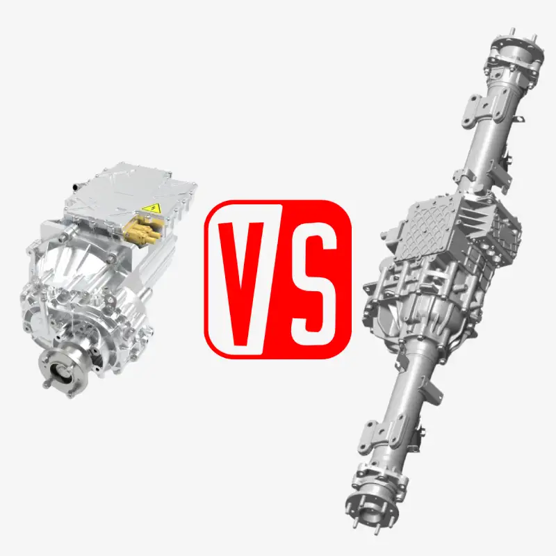
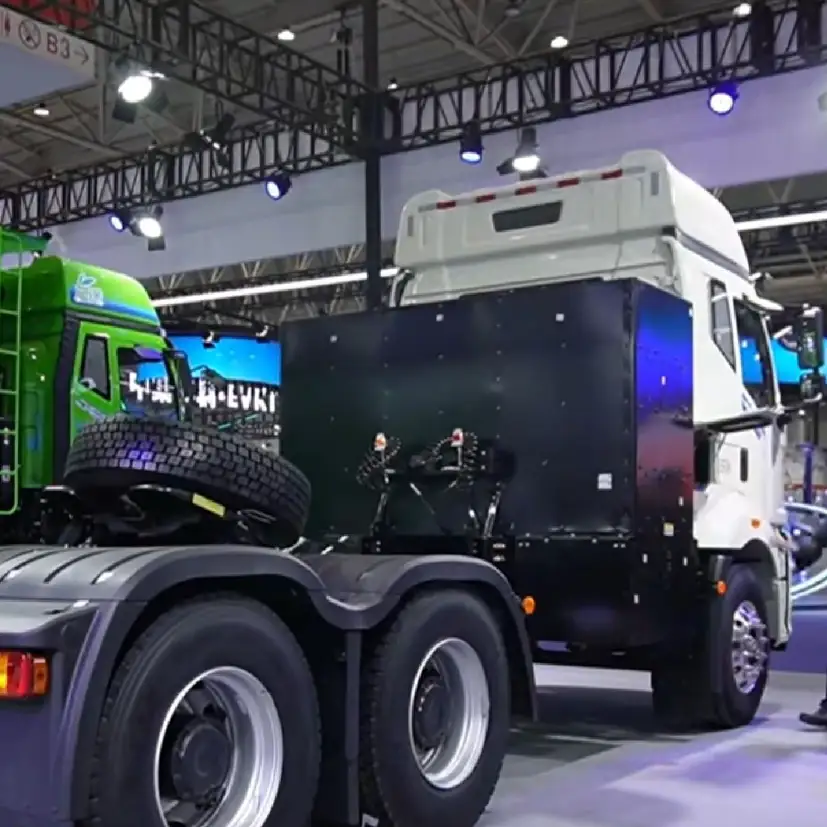
Electric Axle for Truck: Top Use Cases and Benefits The electrification of heavy-duty trucks is accelerating, and with it, the question of which drive system to choose becomes increasingly important. Among the available solutions, the electric axle for truck – also known as an e-axle or electric drive axle – is gaining attention for its performance and efficiency advantages. In this article, we explore the main application scenarios for electric heavy-duty trucks, comparing the benefits and limitations of different drive systems, and offering practical guidance for selecting the right e-axle configuration. Brogen Electric Axle for Heavy-Duty Trucks Electric Heavy-Duty Truck Drive Methods: Central Drive vs. Electric Axle Currently, there are two main drive methods used in electric heavy-duty trucks: the traditional central drive system and the electric axle (e-axle). 1. Central Drive system: Advantages and Limitations A central drive system positions the motor and transmission as a powertrain unit in the middle of the chassis, connected to the drive axle via a driveshaft – similar to the layout of traditional diesel trucks. This design offers high reliability and lower initial cost, as it uses many shared components such as driveshafts, axles, and suspension systems. These parts benefit from mature mass production, reducing overall cost. Additionally, the motor and transmission are mounted using a four-point suspension, minimizing vibration and impact damage. Heavy-Duty Truck with Central Drive Motor However, the system also has notable drawbacks. The central location of the powertrain limits underfloor battery installation, which is essential for achieving high-capacity battery configurations. The low level of component integration adds weight, reducing vehicle efficiency and complicating lightweight design. Furthermore, energy losses occur through the driveshaft and universal joints, resulting in lower transmission efficiency and higher energy consumption. 2. Electric Drive Axle (E-Axle): The Compact and Efficient Solution An electric axle for trucks integrates the motor and transmission into the axle itself, creating a compact, highly efficient system. This layout allows for: Optimized chassis space: Enables large battery packs to be installed under the chassis, lowering the center of gravity and improving vehicle stability. Lightweight design: Reduced component count minimizes overall weight, which is critical for heavy-duty trucks. Higher energy efficiency: Direct power transfer significantly lowers energy losses, reducing electricity consumption. Heavy-Duty Truck with Brogen Electric Axle Despite these advantages, e-axles require a complete redesign and specialized tooling, leading to higher initial costs. Adoption rates remain relatively low – currently under 10% of electric heavy truck applications – but as demand grows, economies of scale are expected to bring prices down. Electric Axle for Truck: Application Scenarios 1. Construction Transport: When E-Axle May Not Be Ideal Examples: 8×4 electric dump trucks, 8×4 electric concrete mixers, and electric mining trucks.  Construction environments often involve harsh road conditions – unpaved roads, gravel, and heavily rutted surfaces. Overloaded trucks can deepen ruts, increasing the risk of undercarriage contact. In these conditions, e-axles are less suitable. Motors and gearboxes integrated into the axle are vulnerable to damage from hard impacts, and since the axle assembly forms part of the unsprung mass, rough terrain can lead to higher vibration and shock loads on the chassis and cabin. For severe off-road environments, a central drive system is typically the better choice. An 8×4 electric dump truck designed for engineering and construction applications, operating under harsh and demanding conditions. 2. Resource Transport: Electric Axle for Truck as a Strong Option Examples: Transport of sand, gravel, coal, and ore. Operating conditions include loading yards with shallow potholes, along with highways and national routes. The risk of grounding is minimal compared to construction sites, making electric drive axles a viable choice. For 6×4 electric heavy trucks, the choice between a centralized drive and an electric axle largely depends on operational needs. If the primary application is resource transportation with routes under 220 km per charge, and cost sensitivity is high while annual mileage is relatively low, with less concern for energy consumption, a centralized drive may be more suitable. However, for fleets with higher annual mileage and stricter energy efficiency requirements, an electric axle is the recommended option due to its superior efficiency and overall performance. Key specifications for e-axles in resource transport: Ground clearance: ≥260 mm Steel housings for motors and gearboxes to improve impact resistance Multi-speed transmission (3-4 gears) to handle steep grades, heavy loads, and varied driving conditions PTO interface for installing hydraulic pumps, essential for tipper applications The electric drive axle features a ground clearance of over 260 mm, a robust cast-steel housing, and is equipped with a power take-off (PTO) interface. 3. Express Delivery & Line-Haul Freight: The Ideal Fit for Electric Axles Many logistics companies are transitioning from diesel to electric heavy-duty trucks for routes under 400 km to reduce operating costs. In this segment, vehicles often cover more than 250,000 km annually, making energy efficiency a critical factor. Some fleets have successfully reduced energy consumption from 1.6 kWh/km to as low as 1.3 kWh/km. The electric heavy-duty truck designed for express and freight transport adopts an underfloor battery layout combined with an electric drive axle. Highway operations make this the perfect scenario for electric drive axles. Recommended configurations include: Multi-motor strategy: Two driven axles with 3-4 motors. At start-up and during acceleration, additional motors provide extra torque. At cruising speed, only one or two motors operate for maximum efficiency. During downhill driving, regenerative braking through multiple motors can recover energy and provide up to 48% of maximum braking power, enhancing safety. Two-speed transmission: Sufficient for highway driving, where steep gradients are not an issue. Lightweight design: Aluminum alloy motor and gearbox housings for improved weight efficiency. Air suspension and wide medium-pressure tires: To reduce vibration and enhance ride comfort. A certain brand of electric heavy-duty truck adopts 2 electric drive axles and 3 motors, with a multi-motor drive strategy. Conclusion: Why the Electric Axle for Truck Is the Future The electric axle is a cornerstone of heavy-duty truck electrification, offering major advantages in efficiency, weight reduction, and flexible vehicle layout. Although initial costs are currently

brogen blade battery solution for heavy truck in australia
Heavy Transport

Blade Battery Solution for Heavy-Duty Trucks in Australia

Blade Battery Solution for Heavy-Duty Trucks in Australia Background Our client is a leading provider of drilling services in Australia, operating across remote and challenging sites where reliability and efficiency are critical. Their fleet of heavy-duty trucks serves multiple functions – from transporting massive drilling rigs to carrying auxiliary equipment that keeps field operations running smoothly. In line with Australia’s national push for decarbonization and their own corporate commitment to sustainability and green drilling practices, the client set a bold target: electrify their heavy-duty trucks. This would not only reduce carbon emissions but also cut operating costs, lower noise levels, and future-proof their business against tightening environmental regulations. However, electrifying heavy trucks in such a demanding industry is no simple task. The client needed a solution that was proven, safe, and immediately deployable without incurring heavy R&D costs or long load times. Challenge: High Energy Demand Meets Space Constraints The first and most significant technical barrier was energy demand versus space availability. Energy requirement: Each truck requires around 500 kWh to operate effectively across long shifts without frequent charging interruptions. Space limitation: The trucks offered limited space for battery installation due to the chassis design and the drilling equipment they carried. When evaluated against conventional LFP battery packs (in standard C-box format): Only 10 boxes could be installed, yielding ~350 kWh at most. To achieve 500 kWh, a new mold would need to be developed – raising development costs, introducing significant delays, and creating risks since the new product would not yet be proven in the market. The client made it clear: they wanted a mature solution that was readily available, cost-effective, and reliable under real-world drilling conditions. Brogen Blade Battery Systems Engineers debugging the battery system Brogen Blade Battery Solution for Heavy-Duty Trucks: Unlocking Efficiency with CTP Technology After a thorough technical evaluation, we proposed a blade battery solution for heavy-duty trucks, leveraging BYD blade cells and CTP (Cell-to-Pack) technology. Key advantages of the blade battery solution: 100 kWh per pack: Each blade battery pack offers higher energy capacity than standard LFP packs. Only five packs required: To achieve the 500 kWh, only five packs were needed – fitting within the truck’s limited installation space. Higher energy density: The CTP design eliminates the need for intermediate modules, improving efficiency and sapce utilization. Proven safety: Blade cells are known for their stability and strong thermal runaway resistance, suitable for demanding applications. By adopting this solution, the client could avoid expensive mold development, minimize project risks, and directly deploy a system that was already market-proven and mature. Our Offering: A Complete System, Not Just Batteries We provided a fully integrated electrification solution, tailored specifically for the client’s drilling fleet. System Components Five 100 kWh Blade Battery Packs (500 kWh total) PDU (Power Distribution Unit) for safe, efficient power control BMS (Battery Management System) with software customized from proven cases BTMS (Battery Thermal Management System) for cooling and heating E-Powertrain (Motor+Controller) for both trucks and retrofit equipment Brogen battery system with PDU Brogen battery system with TMS Beyond Hardware – Our Services Pre-shipment debugging: We thoroughly tested and debugged the entire blade battery system before shipment, ensuring readiness on arrival. Remote technical assistance: Our engineers provided ongoing support to help the client integrate, operate, and maintain the system with confidence. This holistic approach ensured that the client received not only components, but a complete balde battery solution for heavy-duty trucks. Outcome: Reliable Blade Battery Solution for Heavy-Duty Trucks in Australia By deploying our blade battery solution, the client can achieve their electrification goals without incurring unnecessary development risks. 500 kWh target capacity achieved within the limited installation space Significant cost savings by avoiding new mold development Higher system efficiency thanks to CTP technology Reliable performance across wide temperature ranges Reduced carbon emissions, supporting sustainability commitments Currently, the project is still in progress, and we remain committed to helping our client drive fleet electrification while contributing to more sustainable drilling practices. About Brogen At Brogen, we provide advanced EV solutions for global commercial vehicle manufacturers, enabling them to streamline research and development while capitalizing on cutting-edge technology. Our offerings ensure superior efficiency, extended range, and seamless system integration with proven reliability—empowering our partners to lead in the rapidly evolving green mobility landscape. Currently, our EV solutions for battery electric vehicles have been adopted by vehicle manufacturers in countries and regions such as Canada, Türkiye, Brazil, the Philippines, Indonesia, the Middle East, and more. Discover our blade battery solution here: https://brogenevsolution.com/blade-battery-technology-for-electric-commercial-vehicles/ Discover our HCV electrification solution here: https://brogenevsolution.com/heavy-duty-vehicle-electrification-solutions/ Looking for an EV solution for your project? Reach out to us at contact@brogenevsolution.com Contact Us Get in touch with us by sending us an email, using the Whatsapp number below, or filling in the form below. We usually reply within 2 business days. Email: contact@brogenevsolution.com Respond within 1 business day Whatsapp: +8619352173376 Business hours: 9 am to 6 pm, GMT+8, Mon. to Fri. LinkedIn channel Follow us for regular updates > YouTube channel Ev systems introduction & industry insights > ContactFill in the form and we will get in touch with you within 2 business days.Please enable JavaScript in your browser to complete this form.Please enable JavaScript in your browser to complete this form. Name * FirstLast Work Email *Company Name *Your Project Type *– Please select –Car, SUV, MPVBus, coach, trainLCV (pickup truck, light-duty truck, etc.)HCV (heavy-duty truck, tractor, trailer, concrete mixer, etc.)Construction machinery (excavator, forklift, crane, bulldozer, loader, etc.)Vessel, boat, ship, yacht, etc.Others (please write it in the note)Your Interested Solutions *– Please select –Motore-AxleBatteryChassisAuxiliary inverterOBC / DCDC / PDUAir brake compressorEPS / EHPS / SbW / eRCBBTMSOthers (please write it in the note)Do you have other contact info? (Whatsapp, Wechat, Skype, etc.)Please introduce your project and your request here. * Checkbox * I consent to receive updates on products and events from Brogen, and give consent based on Brogen’s Privacy Policy. Submit

high-voltage connectors
Technologies

High-Voltage Connectors: An Overview

High-Voltage Connectors: An Overview In electric vehicle systems, high-voltage connectors serve as the “bridge” for power transmission and are a critical components in ensuring electrical safety. Although small in size, these connectors integrate multiple precision structures and safety features. Let’s break down their key components and see how they ensure safe and reliable performance in high-voltage, high-current environments. 1. Components of High-Voltage Connectors High-voltage connectors are generally composed of the following structures: housing (male and female ends), terminals (male and female terminals), shielding shell, seals (rear, half-end, wire-end, and contact seals), rear protective cover, high-voltage interlock system, and CPA (Connector Position Assurance device). 1.1 Housing The housing acts as the “armor” of the connector, providing both mechanical protection and structural support. It consists of male and female shells that fit together seamlessly. Material strength: Typically made of PA66+GF (glass fiber-reinforced nylon) or PBT, designed to withstand ≥ 125°C (up to 150°C in some applications) and certified to UL94 V-0 for flame resistance. Anti-static surface treatments prevent arcing in high-voltage environments.  Thoughtful design: Male and female housings lock together via snap-fit mechanisms, with mating forces carefully controlled between 80-150 N to ensure both secure connection and ease of operation. 1.2 Therminals If the housing is the armor, the terminals are the heart, responsible for current transmission. Materials: High-purity T2 copper or CuCrZr (copper-chrominum-zirconium alloy) with silver or nickel plating, ensuring contact resistance below 5 mΩ。 Design: Male terminals are typically pin-type, while female terminals use spring or crown structures that apply ≥20 N contact pressure. Even after 500+ mating cycles, resistance variation remains under 10%, ensuring durability. 1.3 Shielding High-voltage transmission can generate EMI (electromagnetic interference) that disrupts vehicle electronics. The shielding enclosure acts as an “invisble barrier”. Performance indicators: Made of copper alloy or aluminum alloy, the shielding efficiency reaches ≥60 dB within the 100 MHz-1 GHz frequency range, equivalent to putting electromagnetic signals into “silent mode”. At the same time, it works with the housing and terminals to form a complete grounding loop, with grounding resistance ≤50 mΩ, effectively eliminating interference risks. Installation details: Fixed to the housing by clips or welding, it achieves a fully enclosed shielding structure, leacing no “escape gap” for electromagnetic signals. 1.4 Sealing System EV batteries are often exposed to harsh environments such as rain and dust. The sealing system acts as a “waterproof shield” for the connectors, building multiple layers of protection: Rear seal: Silicone rubber sealing rings wrap around the cables, achieving IP67  (no water ingress after 30 minutes of immersion at 1m depth) or IP6K9K (resistant to high-pressure water spray). Even when the vehicle drives through water, safety is ensured. Half-end/Wire-end Seal: At the connector interface and cable entry point, O-rings or lip structures fit into housing grooves to form dual protection – like adding a “double safeguard” to every gap. 1.5 Rear Protective Cover The cable interface at the rear of the connector is relatively fragile and prone to damage. The rear protective cover functions like a “safety helmet,” secured to the rear end by threads or clips. It can withstand an axial tensile force of ≥50 N, preventing cable loosening due to pulling, while also enhancing the sealing performance. Some models are further equipped with integrated harness clamps, ensuring a more organized cable layout. 1.6 High-Voltage Interlock System (HVIL) This is an intelligent system that continuously monitors the connection status – serving as the “safety guardian” of the connector. Working principle: A 5V closed-loop circuit is established via micro-switches or Hall sensors. If the connector loosens or disconnects, the circuit is immediately interrupted. The BMS triggers power cut-off protection within 100 ms, cutting the high-voltage supply like an “emergency brake,” fundamentally eliminating the risk of electric shock. 1.7 CPA To prevent issues such as poor contact or overheating caused by incompletely inserted connectors, the CPA (Connector Position Assurance device) was developed. Design details: It typically uses mechanical structures such as plastic clips. When the male and female terminals are fully mated, the CPA provides a clear confirmation – either an audible “click” or a visual color indicator, allowing operators to easily verify the connection status and eliminate the risk of “false mating”. 1.8 Auxiliary Structures In addition to the core components, these auxiliary designs are equally essential: Mis-insertion prevention: The male and female housings feature asymmetric keys, grooves, or other positioning structures – like uniquely shaped keys – preventing connectors of different specifications from being mismated. Thermal management structure: For high-power platforms such as 800 V systems, the connector may include built-in heat sinks or thermally conductive silicone. This controls the temperature rise during high-current transmission to within 50 K, preventing overheating and ensuring stable performance. 2. Key Considerations in High-Voltage Connectors Selection When selecting a high-voltage connector, critical parameters include: Operating temperature: -40°C to 125°C (or higher depending on vehicle requirements). Current capacity: Rated and peak current must meet system requirements. Voltage capacity: Must exceed the maximum battery system voltage. Locking system: Secondary locking (hook+latch) to prevent loosening under vibration. Waterproofing: IP67 / Ip6K9K compliance. Insertion/withdrawal force: Controlled within specified ranges. HVIL support: Determined by system requirements. Conclusion From the housing and terminals to the sealing and interlock systems, every aspect of a high-voltage connector is engineered with safety and reliability in mind. It is this advanced, compact technology that ensures EV batteries can transmit energy efficiently and stably under high-voltage conditions, safeguarding the safe operation of electric vehicles. About Brogen At Brogen, we provide advanced EV solutions for global commercial vehicle manufacturers, enabling them to streamline research and development while capitalizing on cutting-edge technology. Our offerings ensure superior efficiency, extended range, and seamless system integration with proven reliability—empowering our partners to lead in the rapidly evolving green mobility landscape. Currently, our EV solutions for battery electric vehicles have been adopted by vehicle manufacturers in countries and regions such as Canada, Türkiye, Brazil, the Philippines, Indonesia, the Middle East, and more. Discover our HCV electrification solution here: https://brogenevsolution.com/heavy-duty-vehicle-electrification-solutions/ Looking for an EV solution for your project? Reach

Why VCU is necessary for electric vehicles
EV Industry

The Role of the VCU (Vehicle Control Unit) in Electric Vehicles

The Role of the VCU in Electric Vehicles In traditional internal combustion engine (ICE) vehicles, control systems are relatively segmented, with components like the ECU, TCU, ABS, BCM, PEPS, and IPC. In electric vehicles (EVs), the engine and transmission are replaced by the electric motor and battery system. This shift introduces new key systems like the BMS and MCU. Beyond this fundamental shift, EVs also integrate a broad array of high- and low-voltage systems, such as DC/DC converters, onboard chargers (OBC), PTC heaters, and electronic braking systems (EBS), alongside intelligent controllers including the In-Vehicle Infotainment (IVI) system, Thermal Management System (TMS), Telematics Control Unit (T-Box), and Integrated Power Brake (IPB), etc. Why is a VCU Essential for Electric Vehicles? As vehicles evolve, so does the complexity of electronic controls. The number of controllers on board has significantly increased, especially in hybrid electric vehicles, where coordination between the traditional engine system and the electric drivetrain is critical. For example, when the ECU and MCU issue conflicting commands, which system should take priority? This type of decision-making requires a central coordinator – the VCU – to act as the vehicle’s brain. Beyond conflict resolution, EVs also have higher demands for drivability, energy efficiency, and real-time coordination across multiple subsystems. A VCU is necessary to optimize energy use, balance power delivery, improve safety, and ensure consistent performance across various scenarios. VCU Functional Overview The functions of the VCU vary depending on the overall vehicle system architecture. They can be categorized into several functional domains, including vehicle system control, powertrain management, electric power systems, thermal management, diagnostics, communication, and safety monitoring. Key functions include torque control and management, overall energy management, charging and thermal management, fault diagnosis and handling, as well as vehicle status monitoring. 1. Torque Management Torque management governs a vehicle’s acceleration and braking performance – both of which are determined by torque output from the electric motor or engine. The VCU interprets signals from the accelerator and brake pedals (e.g., depth and speed of press), determines the required torque, and coordinates the engine, generator, and coordinates the engine, generator, front and rear drive motors to respond accordingly based on the vehicle’s current operating mode. Case Example: Torque Distribution in AWD EVs All-wheel-drive EVs (as opposed to two-wheel-drive models) feature both front and rear motors. The VCU is responsible for intelligently distributing torque between the two, depending on the efficiency (economy), performance, and stability.   The goal of economic torque distribution is to achieve optimal overall efficiency under the current torque demand. This involves intelligently coordinating dual-, triple, or quad-motor systems to ensure the most efficient power distribution, reducing energy consumption and extending battery range. This strategy is typically applied during steady-speed driving scenarios, such as cruising on highways. In the performance-oriented torque distribution, the load distribution function calculates the optimal torque ratio between the front and rear axles by recognizing current road gradients and the vehicle’s acceleration or deceleration status. By building a dynamic load model, the system automatically adjusts torque distribution during load transfers to make full use of the maximum available tire grip. This reduces wheel slip and enhances the vehicle’s acceleration performance. Performance-oriented torque distribution must especially account for scenarios where a wheel becomes stuck and starts to slip, such as in mud or loose terrain. The basic principle is to actively adjust the torque distribution between the front and rear axles, transferring power to the axle that still has traction when one is slipping. This helps reduce power loss. When alternating slip between the front and rear axles is detected, the system dynamically adjusts torque distribution to maximize available grip, enhancing the vehicle’s ability to escape low-speed traction challenges. Stability-oriented torque distribution focuses on maintaining vehicle stability during steering maneuvers. While systems like ESP are designed to ensure body stability, frequent ESP interventions can lead to an uncomfortable driving experience. By monitoring steering behavior and controlling steering torque, the VCU can proactively adjust front and rear axle torque distribution in real time – before ESP activation – to correct vehicle dynamics. This helps suppress understeer (US) and oversteer (OS), reducing the need for ESP intervention during acceleration and cornering. As a result, it minimizes braking jolts and yaw disturbances, enhancing overall driving comfort and control. When calculating the drive torque, it’s also necessary to consider the vehicle’s driving mode. Under different modes, the accelerator pedal position and vehicle speed are used to first determine the base drive torque. This base drive torque typically corresponds to the ECO mode. If the vehicle is in Normal mode, an additional compensation torque is applied. In Sport mode, a larger compensation value is added to enhance performance. 2. Mode & Energy Management 2.1 Operating Modes In addition to driving modes, vehicles – especially hybrid models – also operate under different operation modes. These include pure electric mode, series (range extender) mode, and parallel mode. While both driving modes and operation modes aim to optimize energy efficiency and power distribution, they differ in how they are set: Driving modes (such as ECO, Normal, and Sport) are manually selected by the driver. Operation modes are automatically determined by the vehicle. In pure electric mode, the vehicle is powered solely by the electric motor using energy from the battery. The engine remains off. In series mode (range extender mode), the engine, generator, and battery are connected in series. When the battery’s state of charge is low, the engine activates the generator to produce electricity, which recharges the battery – effectively extending the vehicle’s range. In parallel mode (direct drive mode), both the engine and the battery provide propulsion simultaneously. Typically, the engine drives one axle while the electric motor powers the other. Since the engine directly contributes to wheel drive in this mode, it is also referred to as direct drive mode.  So how does the vehicle decide whether to use fuel or electricity? The decision of whether to use fuel or electricity in different driving scenarios is made based on energy efficiency.

504kW_620kW electric truck axle brogen electric truck axle
Heavy Transport, Technologies

Heavy-Duty Electric Truck Axles (504 kW / 620 kW)

Heavy-Duty Electric Truck Axles (504 kW / 620 kW) These heavy-duty electric truck axles feature a dual-motor integrated design and are engineered for high-performance applications. With a rated axle load of 13 tons and a maximum system power output of 504 kW or 620 kW, they are capable of meeting the demanding requirements of various heavy-duty commercial vehicles, including 4×2, 6×4, and 8×4 configurations such as municipal vehicles, semi-trucks, and dump trucks. By delivering strong performance and efficiency under heavy-load conditions, these e-axles help significantly reduce both carbon emissions and overall energy consumption. Email: contact@brogenevsolution.com Get Custom Quote Heavy-Duty Electric Truck Axles: Solution Details 1. Solution Features of Our Heavy-Duty Electric Truck Axles Dual Motor + 4-speed AMT Configuration: Adaptable to multiple use cases, from high-capacity long-haul electric semi-trucks to high-torque construction trucks operating under frequent load shifts. Modular Design for Easier Maintenance: High integration of motors and gearbox enables a compact layout and simplifies service and maintenance processes. Transverse Layout Without Hypoid Gear Set: Eliminates the hypoid gear set to reduce mechanical losses, enhancing transmission and regenerative braking efficiency. One-piece Axle Housing with Aluminum Alloy Casing: Integrated cast axle housing offers higher structural strength and sealing performance; aluminum casing helps reduce overall system weight. 2. Technical Parameters Model OESTEA45000Z-1 OESTEA45000Z-2 E-Powertrain Rated Axle Load 13 T (16 T Under Development) Wheel-End Output Torque 45000 N.m 45000 N.m Assembly Weight 985 kg 990 kg Reference Leaf Spring Distance 1018-1050 mm (Adjustable) Wheel Mounting Distance 1837 mm Compatible Suspension Leaf Spring / Air Suspension Motor Parameters Motor Rated/Peak Power 150/252 kW*2 190/310 kW*2 Motor Rated/Peak Torque 285/550 N.m 280/590 N.m Motor Maximum Speed 9000 rpm Transmission Parameters Speed Ratio 4-speed 1st: main transmission 71.0+auxiliary transmission 46.8 2nd: main transmission 36.3+auxiliary transmission 46.8 3rd: main transmission 20.0+auxiliary transmission 13.2 4th: main transmission 10.2+auxiliary transmission 13.2 Brake Brake Specifications Drum brake φ410*220; disc brake 22.5″ Brake Torque 2*18000 N.m (drum brake); 2*22000 N.m (disc brake) Air Brake Chamber Specifications 30/24 (recommended) Other Options Differential Lock Optional PTO Optional PTO for retrofit 3. Advanced AMT Technology – Built for Smarter, Smoother Electric Trucks This electric truck axle platform features a 4-speed AMT. It enables active speed synchronization between the motor and the transmission input shaft, allowing for rapid and smooth gear shifts. By combining gear profile modification with in-depth analysis of casing and shaft tooth deformation, the system achieves optimal meshing conditions, minimizing transmission error and reducing efficiency loss. Faster gear shifting: Reduced shift time improves drivability, especially under frequent stop-and-go scenarios. Higher drivetrain efficiency: Enhances energy use and supports longer driving range. Lower NVH: Quiet and smooth gear transitions improve driving comfort. Lower maintenance cost: Long-life gear oil with no initial oil chaange required; supports extended intervals of 50,000-200,000 km. 4. Key Performance Data Weight reduction vs. direct drive (dual axle): 22% per set Range improvement vs. direct drive: Up to 20% Energy use: 10% less per 100 km at 49t full load vs. industry average Axial space saving: 40% Deployed units (to date): ~13,000 Projected annual production capacity (2025): Over 10,000 units How We Ensure the Reliability of Our Electric Truck Axles Our electric truck axles undergo a rigorous multi-level validation process to guarantee long-term performance, safety, and durability under real-world operating conditions. Component-Level Testing Over 50 tests are conducted on individual components to verify structural integrity, strength, and consistency. These include: Vibration Salt spray Tensile Torsion Hardness Full-dimension inspections Subsystem-Level Testing More than 90 tests are performed across all core subsystems – including the shifting mechanism, gearbox, motor, high/low voltage controllers, wiring harnesses, and software. These tests fall into six major categories: Module validation Functional testing Performance testing Durability testing Reliability testing Environmental resistance System-Level Testing Over 50 tests are carried out at the system level using specialized test benches and real-vehicle road trials, including: High and low temperature cycling Thermal shock testing Salt spray and corrosion resistance Waterproof and dustproof validation Vibration and noise testing System integration and special-condition simulation R&D and Manufacturing Excellence Comprehensive and Integrated R&D Capabilities The R&D team is built on a robust, cross-functional framework encompassing structural engineering, electronic hardware, system architecture, software development, testing, and manufacturing processes. We maintain a full-spectrum development capability that spans from concept design to real-world validation. With in-house expertise in mechanical design, control unit development, computer-aided simulation, bench testing, and complete vehicle road testing, we are equipped to support rapid iteration and innovation across the entire product lifecycle.  Hybrid and pure electric powertrains Transmission systems and controllers Electric motors and motor controllers Shift and clutch actuators Vehicle control units (VCUs) Quality Management & Full Lifecycle Traceability The factory strictly adheres to IATF 16949, ISO 14001, and other international standards, ensuring precise control over every production process and uncompromising quality in every product. The digital management system enables a full lifecycle traceability and control, ensuring that every component is trackable and accountable from production to delivery. In 2025, the e-axle for trucks production capacity is expected to exceed 10,000 units, further demonstrating our ability to scale with quality and consistency. Contact Us Get in touch with us by sending us an email, using the Whatsapp number below, or filling in the form below. We usually reply within 2 business days. Email: contact@brogenevsolution.com Respond within 1 business day Whatsapp: +8619352173376 Business hours: 9 am to 6 pm, GMT+8, Mon. to Fri. LinkedIn channel Follow us for regular updates > YouTube channel Ev systems introduction & industry insights > ContactFill in the form and we will get in touch with you within 2 business days.Please enable JavaScript in your browser to complete this form.Please enable JavaScript in your browser to complete this form. Name * FirstLast Work Email *Company Name *Your Project Type *– Please select –Car, SUV, MPVBus, coach, trainLCV (pickup truck, light-duty truck, etc.)HCV (heavy-duty truck, tractor, trailer, concrete mixer, etc.)Construction machinery (excavator, forklift, crane, bulldozer, loader, etc.)Vessel, boat, ship, yacht, etc.Others (please write it in the note)Your Interested Solutions *– Please select –Motore-AxleBatteryChassisAuxiliary inverterOBC / DCDC / PDUAir brake

Scroll to Top