High Voltage Wire Harnesses in EVs: Key Design Principles
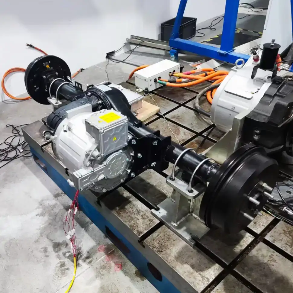
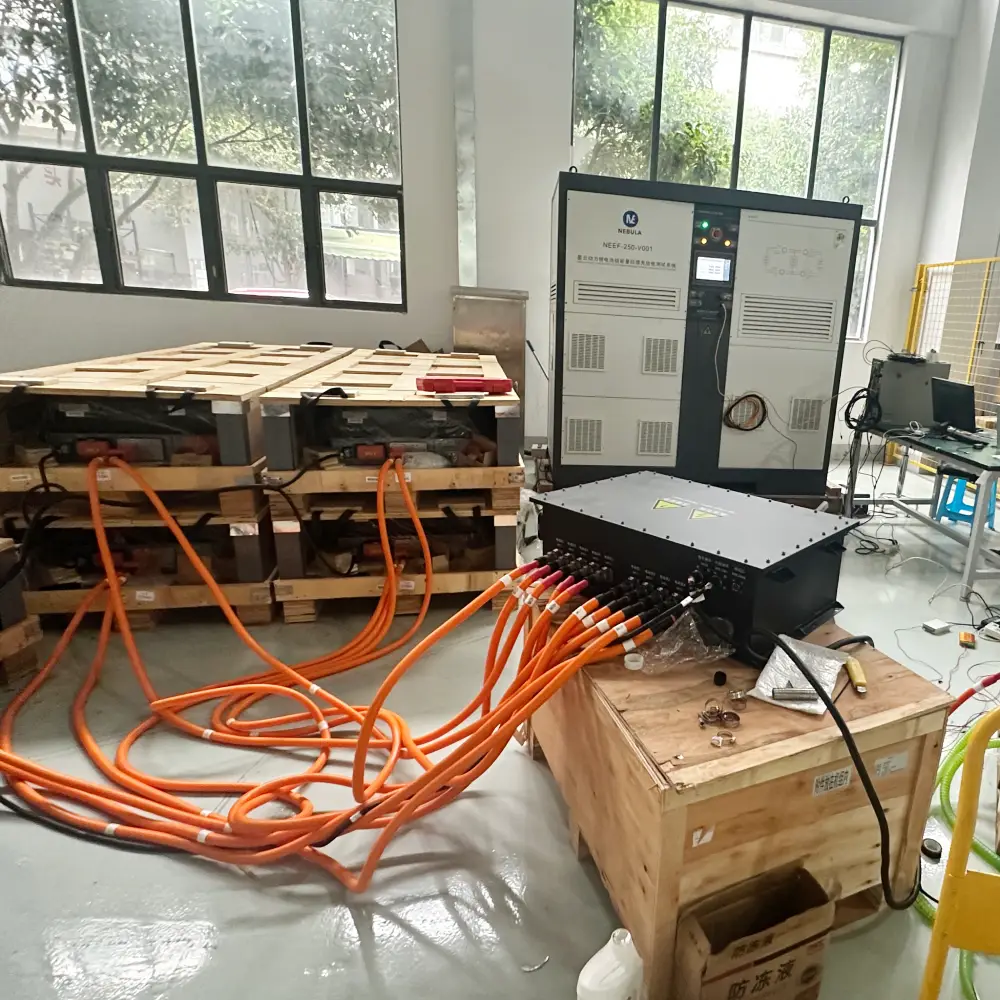
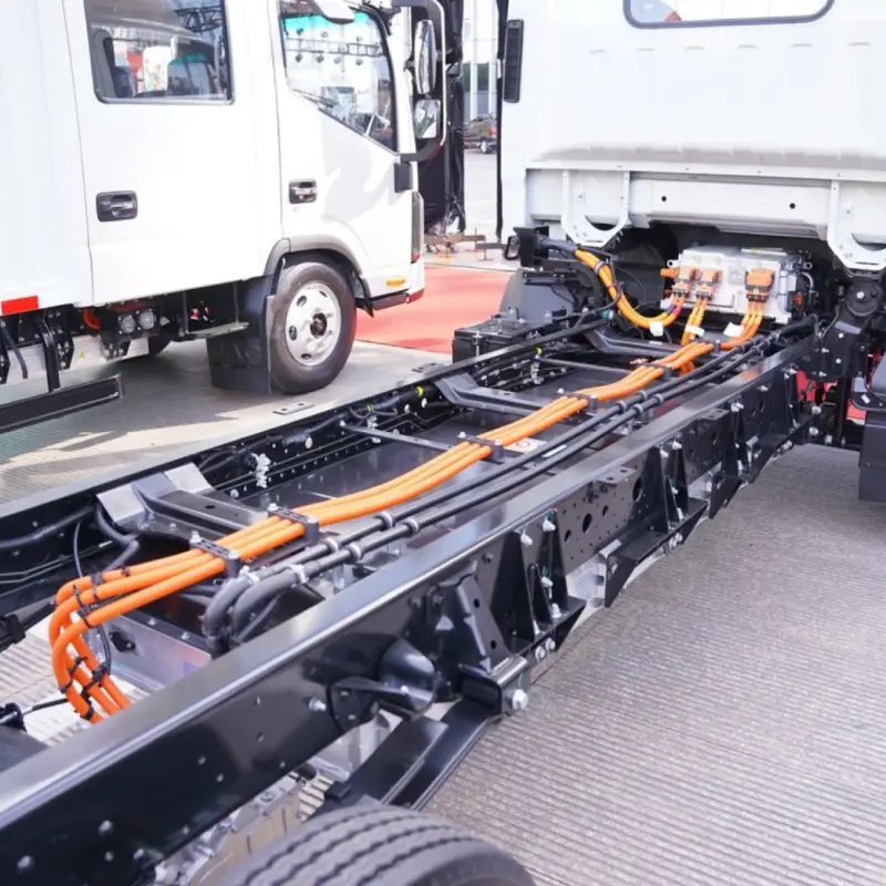
High Voltage Wire Harnesses in Electric Vehicles: Key Design Principles High voltage wire harnesses play a critical role in electric vehicles, transmitting high voltage and large currents between essential components like the battery pack, high-voltage PDU, inverter, and traction motor. These harnesses ensure efficient energy transfer, enabling EV systems to operate in perfect synchronization. Proper installation and secure mounting of high voltage wire harnesses is essential for safety, reliability, and performance.. 1. Routing Principles for High Voltage Wire Harnesses Before discussing installation and fixation, it’s crucial to understand routing principles. 1.1 Proximity Principle The routing should follow the shortest feasible path to minimize voltage drop and weight, which supports efficiency and cost reduction. 1.2 Ease of Assembly The overall design and fixation method of the EV wiring harness should prioritize ease of assembly to ensure simple and efficient installation. Connector Mounting and Fixation: Allow adequate length and installation space for connectors to facilitate smooth operations. Harness and Component Fixation: Ensure sufficient clearance for fastening tools, maintaining at least a 50 mm gap from the center of the nut for safe operation. Harness Clip Fixation: Position harness clips strategically to minimize quantity while ensuring secure attachment. 1.3 Maintainability The principle of good maintainability in automotive wiring harness design means ensuring ease of maintenance and repair throughout the vehicle’s lifecycle. The layout should allow faults to be diagnosed and repaired in the shortest possible time while minimizing the impact on other components. Connector Placement and Fixation: Connectors should be positioned within easy reach. For connectors that require single-hand operation, the opposite end should be securely fixed. Avoiding Misconnection and Providing Extra Length: Connectors on the same component should be arranged to prevent incorrect mating. The end of the wiring harness should have a reserved length. For example, high-voltage wires near the connector tail must not be bent or stressed, must not be twisted, and should be secured within 120 mm. Fuse Box Harness Allowance: The wiring harness for the fuse box should have sufficient slack to provide adequate operating space during maintenance. 1.4 Safety and Reliability Ensuring the safe and stable operation of the electrical system – and by extension, the proper functioning of all vehicle electrical equipment – is the ultimate goal of wiring harness design. Harness Fixation Location: Whenever possible, secure wiring along edges, channels, or areas that are less likely to be touched to prevent external forces from damaging the harness. Avoid Sharp Bends: When bends are unavoidable, allow adequate space and apply special fixation at the bend points. Ensure no kinks or excessive stress occur. Prevent Cable Damage: Harnesses passing through holes must be protected with sleeves, grommets, or protective tape to avoid abrasion. In the event of a collision, the harness should not be crushed, as this could lead to rupture and short circuits. High-Voltage Wire Harnesses Wrapping Materials Maintain Design Allowance: For main branches, ensure a sufficient bending radius to avoid tight routing that complicates assembly. Do not pull harnesses too tightly during installation, as vibrations during driving could shift fixation points. Avoid High-Vibration Zones: High-voltage harnesses should be routed away from major vibration sources such as air compressors or water pumps. If unavoidable, allow adequate slack based on vibration amplitude and the maximum motion envelope of moving parts to prevent tension on the harness. Avoid High-Temperature Zones: Keep harnesses away from high-temperature components such as compressors, brake lines, steering pumps, or oil pipes to prevent insulation melting or accelerated aging, which could lead to exposed conductors and short circuits. Maintain Bend Radius for High-Voltage Cables: Over-bending high voltage wire harnesses increases resistance, causing higher voltage drop and accelerating insulation aging or cracking. The minimum bend radius should be at least 4x the cable’s outer diameter. High-voltage cables exiting connectors must remain straight, without bending, twisting, or stress. Correct Connector Layout Example (Left) | Incorrect Connector Layout Example (Right) Sealing and Waterproofing: To enhance mechanical protection and ensure dust and water resistance, use seals or gaskets at connector interfaces and cable entry points. This prevents moisture and debris ingress, ensuring insulation integrity and avoiding short circuits, arcing, or leakage. 1.5 Aesthetic and Organized Routing Hidden or Aligned: Harness routing should prioritize a neat and aesthetic layout, either by concealing the harness or arranging it in a horizontal and vertical orientation. The routing should follow the direction of the adjacent components and, in the projected view, maintain a straight, grid-like arrangement wherever possible. Diagonal paths and crossing layouts should be avoided. The harness should align with surrounding harnesses, water pipes, air pipes, and oil pipes to maintain visual uniformity and an overall clean appearance. 2. Installation and Fixation Design for High Voltage Wire Harnesses 2.1 Planning of Harness Fixation Points The distribution of fixation points is the foundation for securing high-voltage harnesses and directly impacts their stability. Generally, the placement of these points should be determined based on factors such as harness length, routing, and bending positions. For longer harnesses, additional fixation points are necessary to prevent displacement caused by vibrations during vehicle operation. At bends, fixation points should be placed at both the start and end of the curve to avoid excessive stress on the harness in these areas. Securing High-Voltage Wiring Harness at Bend Points The spacing requirements for fixation points vary according to the cross-sectional area of the harness. Typically: For smaller harnesses (≤16 mm²), the spacing can be slightly larger but should not exceed 300 mm. For larger harnesses (>16 mm²), due to greater weight and mechanical stress, the spacing should be kept within 200 mm. Additionally: The distance from the high-voltage connector outlet to the first fixation point should be ≤100 mm. The clearance between the high-voltage harness and heat sources should be >200 mm. Through proper planning of fixation points, issues such as shaking or displacement during vehicle operation can be effectively avoided, ensuring stable and reliable power transmission. 2.2 Selection of Fixation Methods In the installation of high-voltage harnesses for electric vehicles, common fixation methods include cable ties, clips,