Public Transportation

electric bus powertrain
Public Transportation, Technologies

Integrated Electric Bus Powertrain Axle Assembly Design

Integrated Electric Bus Powertrain Axle Assembly Design Introduction to Electric Bus Powertrain Development Electric buses have increasingly been recognized worldwide as a leading direction in EV development. As the consumption of non-renewable resources accelerates, the automotive industry’s shift toward electrification is becoming even more pronounced. However, due to current limitations in energy storage technology, electric vehicles continue to lag behind traditional vehicles in areas such as driving range, battery lifespan, and charging convenience. Consequently, pure battery electric buses (BEBs) tailored to specific routes and operating conditions are at the forefront of pilot programs. In recent years, the electrification of public transportation fleets in major cities around the world has gained significant momentum. With substantial investments flowing into the pure electric bus sector, it is critical to harness emerging technologies to strengthen product competitiveness. Among these advancements, the integration of electric motor and drive axle design has notably enhanced the performance of electric buses and has become a key focus in EV safety development. Overview of Integrated Electric Bus Powertrain Axle Assembly Traditional bus powertrains consist of an engine, transmission, driveshaft, and axle assemblies. As the electric bus powertrain industry continues to evolve, many manufacturers initially adopted transitional solutions — replacing the internal combustion engine with an electric motor while largely retaining the traditional mechanical layout, as illustrated in Figure 1. However, this approach introduces several challenges: Low transmission efficiency: Overall system efficiency remains below 80%. Poor system integration: The design conflicts with the industry’s ongoing lightweighting initiatives. Limited regenerative braking performance: Due to the inherent limitations of traditional bevel gear axles, brake energy recovery rates are typically below 30%. The new generation electric bus powertrain layout proposed in this paper effectively overcomes these shortcomings (Figure 2). In this new design, the electric motor is fully integrated into the drive axle assembly, eliminating the need for separately mounted motors, suspension components, and driveshafts within the vehicle frame. This integrated configuration simplifies vehicle layout and installation. The suspension system mounts directly to the axle housing, and the battery packaging is optimized, significantly improving internal space utilization. Nevertheless, engineering challenges remain. Precisely determining the torque axis is complex due to factors such as vehicle and drivetrain layout, packaging constraints, and the mechanical characteristics of rubber isolators, all of which affect the compression-to-shear stiffness ratio and complicate accurate positioning of the fore-aft mounting centers along the torque shaft. System Design of the Integrated Electric Bus Powertrain Axle Assembly Taking an 8.5-meter pure electric bus as a design example: Current mainstream design: Uses a low-speed, permanent magnet synchronous, water-cooled electric motor. Max power: 300 kW Max torque: 2070 Nm Speed: 4000 rpm Axle load: 8 tons Gear ratio: 5.857 Motor weight: 550 kg Driveshaft weight: 40 kg Maximum wheel driving torque: 2070 × 5.857 = 12100 Nm The suspension system’s natural frequency is below 30 Hz. New high-speed design: Introduces a high-speed permanent magnet synchronous, water-cooled motor: Power: 205 kW Torque: 500 Nm Max speed: 12,000 rpm Motor weight: 102 kg Axle weight: 580 kg (with no driveshaft required) Gear ratio: 24.8 Maximum wheel driving torque: 500 × 24.8 = 12400 Nm In traditional axles, the engine layout perpendicular to the driving direction necessitates the use of bevel gears to redirect power. Bevel gear manufacturing limitations mean that convex and concave gear sides have different accuracies. During regenerative braking, if over 30% of braking energy is recovered, the concave gear side’s insufficient precision can cause gear surface damage or even failure. To address this, the new solution arranges the motor parallel to the vehicle’s driving direction, eliminating the need for bevel gears. All gears are cylindrical gears, which are easier to design and manufacture with high precision, improving durability and supporting more efficient brake energy recovery. Weight Comparison Category Weight (kg) Traditional pure electric design 300 + 550 + 40 = 890 kg Integrated axle motor design 102 + 580 = 682 kg Weight saving 890 – 682 = 208 kg Application of Integrated Electric Bus Powertrain Axle Assembly By integrating the motor and axle into a unified powertrain system, there is no longer a need to reserve separate space for the motor. This design reduces the rear suspension space requirements, as shown below, and significantly improves passenger cabin space by increasing the distance between the front and rear doors. Performance Comparison Between Integrated and Traditional Electric Bus Powertrains The integrated electric bus powertrain offers the following advantages over traditional designs: Higher system integration:The axle self-assembles with the powertrain, simplifying vehicle layout and improving transmission efficiency. Enhanced regenerative braking:Brake energy recovery capacity can reach up to 100%. Significant weight reduction:Lightweighting of approximately 208 kg for an 8.5-meter electric bus. Improved vibration isolation and vehicle stability:Experimental tests confirm enhanced ride quality and comfort. Conclusion This study explores an innovative electric bus powertrain layout that significantly improves electric vehicle performance. Through ultra-short rear suspension designs and system lightweighting, the proposed integrated axle motor assembly enhances vehicle energy efficiency (EKG indicators) and extends the continuous driving range. The results demonstrate higher transmission efficiency, superior regenerative braking capabilities, and reveal the future electrification trends for heavy-duty vehicles. Discover our integrated electric bus powertrain (electric bus axle) here: https://brogenevsolution.com/electric-axle-for-bus/ Business inquiry: contact@BrogenEVSolution.com Or you can complete the table below to get in touch with us. Contact Us Get in touch with us by sending us an email, using the Whatsapp number below, or filling in the form below. We usually reply within 2 business days. Email: contact@brogenevsolution.com Respond within 1 business day Whatsapp: +8619352173376 Business hours: 9 am to 6 pm, GMT+8, Mon. to Fri. LinkedIn channel Follow us for regular updates > YouTube channel Ev systems introduction & industry insights > ContactFill in the form and we will get in touch with you within 2 business days.Please enable JavaScript in your browser to complete this form.Please enable JavaScript in your browser to complete this form. Name * FirstLast Work Email *Company Name *Your Project Type *– Please select –Car, SUV, MPVBus, coach, trainLCV (pickup truck, light-duty truck, etc.)HCV (heavy-duty

BYD electric bus in europe
Industry Insight, Public Transportation

Analysis: Why BYD’s Electric Buses Are Gaining Ground in Europe’s Public Transport Landscape

Analysis: Why BYD’s Electric Buses Are Gaining Ground in Europe’s Public Transport Landscape From Tromsø in the Arctic Circle to the sun-soaked streets of Barcelona, BYD electric buses have become a familiar sight across Europe. As the continent pushes forward on its green mobility transition, BYD’s battery-electric buses (BEBs) are fast becoming the new “green arteries” of modern cities. With over 6,500 electric bus orders across 110+ cities in 20 countries, and more than 550 million kilometers of cumulative driving range (equivalent to reducing 599,000 tons of CO₂ emissions), BYD has reshaped how Europe moves since entering the market in 2013. But how did a Chinese manufacturer break into one of the world’s most competitive public transport markets—and win trust? Building Trust: From Skepticism to Leadership When BYD introduced its first K9 electric buses in Europe in 2013, the response was filled with doubt. “Will Chinese batteries withstand our climate?” was a common question from European transit authorities. A decade later, BYD buses are operating reliably in sub-zero temperatures—surviving -40°C winters in Northern Sweden with zero breakdowns over five years, and achieving a 99.8% punctuality rate in London, outperforming diesel fleets. Today, European customers are no longer asking “if” BYD buses can perform, but “when” the next model will be delivered. That transformation—from trial orders to mass procurement to winning tenders—is the result of a carefully executed, long-term market strategy. A Holistic Zero-Carbon Ecosystem In Amsterdam, a typical commuter’s day might begin on a BYD electric bus, continue with a business meeting in a Denza D9 EV, and end by charging their home solar battery system, repurposed from a retired BYD bus battery. This is the zero-carbon ecosystem BYD is building across Europe: Commercial vehicles leading the way: Electric buses operating in 80% of Europe’s major public transport systems. Passenger cars following suit: The premium Denza MPV brand is now a favorite among German taxi companies. Energy loop closure: Retired bus batteries are repurposed into energy storage systems for households. “We’re not just selling vehicles—we’re offering a complete zero-emission mobility solution,” emphasized BYD’s European brand lead. In Bergen, Norway, this “ecosystem model” is already proving effective: BYD secured both the city’s public bus contract and a fleet agreement with the largest local car rental company, creating a robust green mobility network. Tailored Engineering for Every City Three key innovations set BYD’s buses apart in Europe: Cold Climate Mode: Self-heating batteries that improve start-up efficiency by 40% in -30°C weather; heated floors in Nordic editions reduce energy consumption by 15%. Mountain Algorithms: Swiss models include an “Alpine Mode” with regenerative braking on long descents; Lisbon versions boost hill-climbing power by 20%. Smart Maintenance: Predictive diagnostics identify faults 14 days in advance, cutting repair costs by 37%, according to data from Brussels operations. “These aren’t off-the-shelf features,” explained a BYD engineer. “We developed them city by city.” Before entering Spain, the team spent three months mapping every steep street in Madrid, eventually creating the bespoke “Iberia Mode.” The European Carbon Calculator In Hamburg, 200 BYD buses save enough diesel annually to fill 1.5 Olympic-sized swimming pools. In Rennes, France, the city’s full electrification efforts earned it the EU’s Green Capital award and secured €200 million in additional environmental funding. Across Europe, cities are discovering that electrification brings both environmental and political capital.   The Road Ahead: From Electrification to Full Zero-Carbon Transport Chains In 2024, BYD’s European presence is reaching a new milestone. Its Hungarian factory will produce 1,000 buses annually, with the first “Made-in-Europe” units rolling out soon. “The real competition starts now,” said a transport policy expert. “When Chinese brands begin shaping the standards, the rules of the game change.” In fact, six provisions in the latest EU electric bus safety regulations are based directly on BYD technologies. Conclusion: Lessons for European OEMs BYD’s European journey shows what’s possible with strategic persistence, local customization, and technological leadership. From Copenhagen airport to the city center, newly deployed BYD buses now carry the Danish phrase “Grøn Fremtid”—“Green Future”—on their sides. It’s an apt summary of a vision where Chinese EV technologies are no longer learners, but standard-setters. For European OEMs and bus manufacturers looking to stay ahead in the competitive electric public transport market, one thing is clear: a zero-emission future belongs to those who innovate fast, adapt locally, and build systems—not just vehicles. Want to lead the future of electric buses in Europe?Our team at Brogen offers customized electric bus system solutions designed for European conditions—covering everything from electric axles and motors to battery systems, controllers, and power distribution units. Let’s build the next “Green Artery” of Europe together. Discover our Public Transport Electrification Solutions here: https://brogenevsolution.com/public-transport-electrification-solutions/ Business inquiry: contact@BrogenEVSolution.com Or you can complete the table below to get in touch with us. Contact Us Get in touch with us by sending us an email, using the Whatsapp number below, or filling in the form below. We usually reply within 2 business days. Email: contact@brogenevsolution.com Respond within 1 business day Whatsapp: +8619352173376 Business hours: 9 am to 6 pm, GMT+8, Mon. to Fri. LinkedIn channel Follow us for regular updates > YouTube channel Ev systems introduction & industry insights > ContactFill in the form and we will get in touch with you within 2 business days.Please enable JavaScript in your browser to complete this form.Please enable JavaScript in your browser to complete this form. Name * FirstLast Work Email *Company Name *Your Project Type *– Please select –Car, SUV, MPVBus, coach, trainLCV (pickup truck, light-duty truck, etc.)HCV (heavy-duty truck, tractor, trailer, concrete mixer, etc.)Construction machinery (excavator, forklift, crane, bulldozer, loader, etc.)Vessel, boat, ship, yacht, etc.Others (please write it in the note)Your Interested Solutions *– Please select –Motore-AxleBatteryChassisAuxiliary inverterOBC / DCDC / PDUAir brake compressorEPS / EHPS / SbW / eRCBBTMSOthers (please write it in the note)Do you have other contact info? (Whatsapp, Wechat, Skype, etc.)Please introduce your project and your request here. * Checkbox * I consent to receive updates on products and events from Brogen, and give consent based

Selection and Layout of Battery Thermal Management Systems BTMS for Electric Buses
Industry Insight, Public Transportation

Battery Thermal Management System (BTMS) for Electric Buses: Selection and Integration Strategy

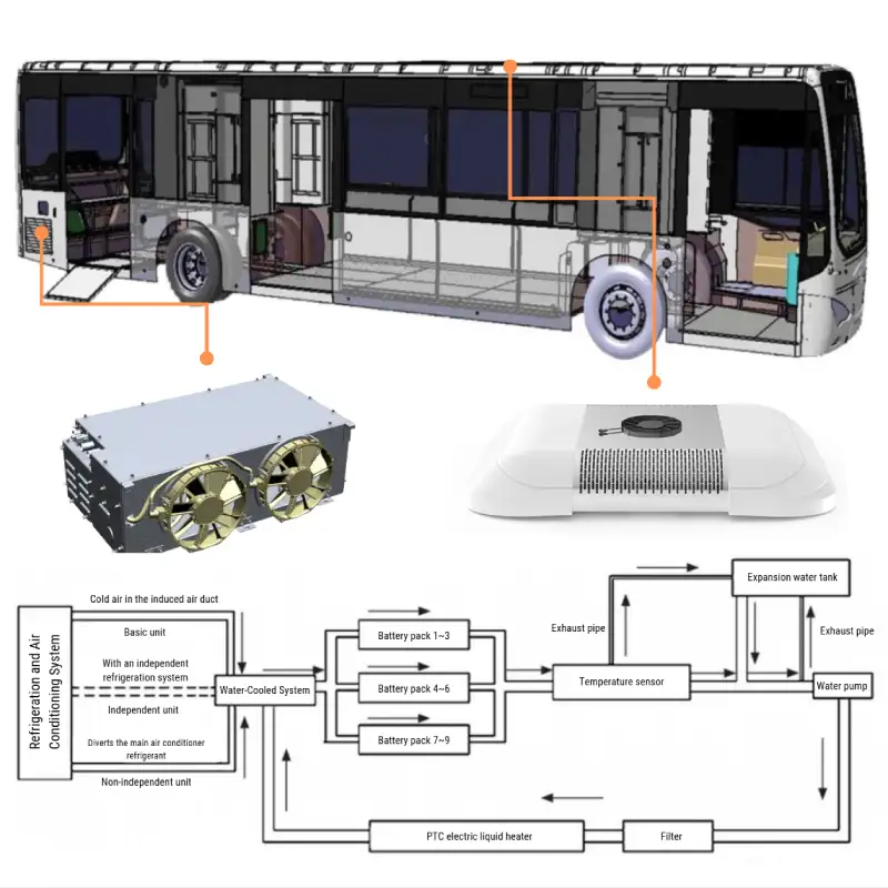
Battery Thermal Management System (BTMS) for Electric Buses: Selection and Integration Strategy This article introduces common types and configurations of battery thermal management systems (BTMS) for electric buses. As a critical component of electric buses, the BTMS acts as a “guardian” for the battery, ensuring its performance, safety, and longevity. Therefore, a thorough understanding of the different BTMS types and layouts is essential for practical applications. 1. Selection of the Battery Thermal Management System (BTMS) for Electric Buses The battery thermal management system (BTMS) for electric buses regulates the battery’s operating temperature through external equipment, ensuring that the battery always functions within an optimal temperature range. For lithium batteries, the ideal working temperature is between 20°C and 35°C. When the temperature is too low, battery capacity decreases, and power performance declines. When the temperature is too high, the risk of self-discharge increases, and internal side reactions become more frequent, reducing the available battery capacity and decreasing its lifespan and efficiency. Battery thermal management involves cooling the battery in summer to prevent irreversible thermal reactions that could cause safety issues. In winter, it heats the battery to maintain charging and discharging performance while preventing lithium plating at the anode, which could lead to internal short circuits. The selection of battery thermal management equipment should be based on the vehicle’s operating conditions and battery placement to meet the thermal management requirements. Ensuring that the battery remains in an optimal “comfort zone” helps improve its lifespan. Below are common battery thermal management solutions for buses. 1.1 Basic Battery Thermal Management System The basic BTMS unit directs air-conditioned cold air into the unit to exchange heat with circulating antifreeze for cooling. For heating, it uses an electric liquid heater to warm the antifreeze, which is then circulated to the battery pack. After cooling or heating, the antifreeze enters the battery compartment to regulate the battery’s temperature, keeping it within the desired range. Compared to independent and non-independent BTMS units, the basic unit is the most cost-effective and simplest system. It is also relatively safe, as it does not use a vapor compression refrigeration cycle. However, since it relies on the vehicle’s air conditioning system for cooling, it requires the installation of a cooling system. Additionally, when the cooling system first starts, the cold air temperature is relatively high, leading to poor initial cooling performance. The cooling power is generally below 2 kW, making this solution suitable for hybrid buses with slow-charging battery packs and low charge/discharge rates. Basic BTMS Unit System Schematic Diagram Basic BTMS Unit System Structure 1.2 Independent Battery Thermal Management System The independent BTMS unit includes its own compressor, condenser, and plate heat exchanger, forming a separate cooling cycle. Cooling is achieved by exchanging heat between low-temperature, low-pressure refrigerant and the circulating antifreeze in the heat exchanger. Heating is done via an electric liquid heater that warms the antifreeze before circulating it to the battery pack. Compared to the non-independent unit, this system has an additional dedicated compressor and condenser, increasing costs. However, since it operates independently, it features simpler control logic and fewer refrigerant connectors, making it relatively safer. The cooling power of an independent unit is generally above 2 kW, making it suitable for hybrid and fully electric buses with fast-charging battery packs and high charge/discharge rates. Independent BTMS Unit System Schematic Diagram 1.3 Non-Independent Battery Thermal Management System The non-independent BTMS utilizes an external cooling system, where low-temperature, low-pressure refrigerant produced by another cooling device exchanges heat with circulating antifreeze in a plate heat exchanger. Heating is performed using an electric liquid heater, which warms the antifreeze before it circulates to the battery pack. Since it shares the vehicle’s cooling system, it requires the installation of a refrigeration system. Additionally, due to the variable-frequency compressor’s minimum frequency limit, the power output is relatively high, typically above 6 kW. Compared to an independent unit, this system has a more complex control logic due to potential conflicts between battery thermal management and vehicle air conditioning demands. The non-independent unit is suitable for fully electric buses with fast-charging battery packs and high charge/discharge rates. Non-Independent Unit System Schematic Diagram 2. Layout of Battery Thermal Management System for Electric Buses 2.1 Basic Principles for BTMS Layout The layout of battery thermal management equipment is closely related to the placement of the battery itself. The following principles should be followed when arranging the equipment: Proximity to the battery placement – The thermal management equipment should be installed as close as possible to the battery, whether the battery is mounted on the top, bottom, or rear of the vehicle. At the same time, potential disadvantages associated with the chosen placement should be minimized. Installation requirements for different types of equipment – For independent battery thermal management systems, vibration-damping rubber pads should be added during installation. The condenser’s air intake and exhaust must remain unobstructed to prevent air recirculation. For basic thermal management systems, cold air should be drawn from the vehicle’s refrigeration system. The air intake point should be positioned as close as possible to the evaporator outlet of the main cooling system. Coolant circulation considerations – The water pump inlet for circulating antifreeze through the battery box’s cooling plate should be located as close as possible to the expansion tank, which maintains system pressure and allows antifreeze refilling. The expansion tank must be placed at the highest point of the battery cooling system. Additionally, an air vent pipe should be included to remove air released during heating or cooling, preventing difficulties in adding antifreeze. Cooling circuit for multiple battery groups – To minimize temperature differences between different battery packs, the cooling circuit should be arranged in a parallel configuration. Each individual branch should not exceed three battery boxes per loop. PTC Electric Liquid Heater Placement – If a PTC electric liquid heater is installed, it should be positioned downstream of the water pump at a lower point in the cooling circuit. It must not be placed at the highest point of the coolant loop. Optimization

battery thermal management system for electric bus
Public Transportation, Technologies

Battery Thermal Management for Electric Bus: An Overview

Battery Thermal Management for Electric Buses: An Overview This article explores the structure and working principles of common battery thermal management in battery electric buses (BEB), offering valuable insights for their design. The performance of the traction battery system is a key factor in a battery electric bus’s overall efficiency, range, and reliability. Since battery temperature directly affects performance, lifespan, and safety, a well-designed thermal management system is crucial for optimizing operation and ensuring long-term durability. 1. Different Types of Battery Thermal Management Effective battery thermal management ensures optimal performance and safety by regulating temperature under varying conditions. This includes cooling the battery during high temperatures to prevent overheating and heating it in low temperatures to maintain efficiency and reliability. 1.1 Battery Cooling Methods Battery cooling is essential for maintaining performance and safety in electric buses. The most common cooling methods for EV  batteries include natural air cooling, forced air cooling, liquid cooling, and direct refrigerant cooling. The air cooling method features a simple structure, lightweight design, low cost, and no risks of harmful gas accumulation or liquid leakage. However, its drawbacks include low heat dissipation efficiency, difficulty in sealing design, and poor dustproof and waterproof performance. Depending on whether additional devices are used to introduce cooling air, the air cooling system is divied into natural air cooling and forced air cooling:  Natural Air Cooling & Forced Air Cooling Natural Air Cooling: It’s a method of utilizing the wind generated by the vehicle’s movement to flow through a diversion pipe and directly cool the battery pack. This approach requires no auxiliary motors, offers a simple structure, and is easy to use. However, the cooling airflow is subject to instability due to fluctuations in vehicle speed, resulting in variable cooling performance. Additionally, air has low heat capacity and thermal conductivity, which limits the efficiency of heat transfer. Natural air cooling is best suited for vehicles with low discharge rates and minimal heat generation in their power batteries. Forced Air Cooling: It directly introduces cabin air, natural air, or external convection air into the battery compartment to cool the battery pack. This cooling method has relatively poor performance, the largest system volume, and a high risk of water ingress. However, it is lightweight, easy to control, has low energy consumption, relatively low system costs, is relatively easy to implement, and offers high process reliability. Liquid Cooling Liquid Cooling: It utilizes convective heat transfer through a coolant to dissipate the heat generated by the battery, effectively lowering its temperature. It’s currently the most widely adopted cooling solution in the market. Compared to air cooling, liquid cooling systems – using coolant as the heat transfer medium – offer significantly higher specific heat capacity and thermal conductivity. Additionally, in low-temperature environments, the system can also provide heating for the battery pack. However, the primary drawbacks of liquid cooling include increased structural complexity, added battery system weight, and higher overall system costs. Direct Refrigerant Cooling Direct Refrigerant Cooling: Also known as direct cooling or refrigerant-based cooling, integrates the battery thermal management system with the vehicle’s air conditioning system. In this approach, an evaporator in the refrigerant loop functions as the battery’s direct cooling plate, simplifying the overall system. It minimizes heat exchange losses, resulting in a rapid thermal response. And the design eliminates the need for a separate battery cooling loop, reducing components like the coolant pump, piping, and chiller, leading to a more space-efficeint, lightweight thermal management system. A comparison of different cooling methods is as follows: Comparison Item Natural Cooling Forced Air Cooling Liquid Cooling Direct Cooling Working Principle Natural air convection Forced air convection Forced liquid convection Phase-change cooling Heat Transfer Coefficient (W/m²K) 5-25 25-100 500-15000 2500-25000 Heat Dissipation Efficiency Poor High High Very High Temperature Uniformity Good without external heat sources, otherwise poor Poor (especially at inlet and outlet) Good Good Installation Environment Adaptability Poor (requires external insulation and ventilation) Fair (dependent on inlet and outlet air structure) Good Good Suitability for High/Low Temperatures Poor (conflict between auxiliary heating/insulation and heat dissipation) Poor (conflict between auxiliary heating/insulation and heat dissipation) Good (capable of both heating and cooling) Poor (requires additional auxiliary heating, difficult to control heat pump) Complexity Simplest Moderate Complex Complex Energy Consumption None High Low (easy to implement insulation) Low (high efficiency) Cost Low Relatively High High (can be optimized) High 1.2 Battery Heating Methods To maintain optimal performance in cold conditions, EV traction batteries require heating. The most common battery heating methods include: Integrated Electric Heating Film: A thin electric heating film integrated inside the battery pack directly heats the battery cells. Performance: Above 0°C: works well, requires no additional space, consumes no energy when inactive, and is cost-effective. Below 0°C: heating efficiency drops significantly, making it unsuitable for extremely cold environments. Advantages: Space savings and easy to implement; low system cost and no additional control needed. Limitations: Ineffective in freezing temperatures, leading to limited adoption in colder climates. Liquid-Based Heating System: An electric liquid heater is integrated into the thermal management system’s coolant circuit to heat the antifreeze, which then circulates to warm the battery pack. Performance: Provides efficient and uniform heating, making it the preferred method in colder regions. Advantages: Compact system design with minimal space requirements; mature and reliable technology with well-established control mechanisms; high heating efficiency, ensuring stable battery operation in low temperatures Limitations: Higher system cost compared to electric heating films. Due to its efficiency and reliability, liquid heating is currently the most commonly used battery heating solution. Comparison Item Electric Heating Film Liquid Heating Heating Characteristics Constant power heating Convective/conductive heating Space constraints (Thickness) 0.3~2 mm Integrated into the liquid heating system Heating Rate 0.15~0.3°C/min 0.3~0.6°C/min Uniformity (Battery Temperature Difference) ≈8°C ≤5°C 2. Structure and Working Principles of Battery Thermal Management Systems To maintain optimal performance and longevity, EV traction batteries in electric buses operate within an ideal temperature range of 25°C ± 5°C, regardless of seasonal variations. In winter, the battery thermal management system heats the coolant to maintain the target

160kw electric axle for buses
Public Transportation, Technologies

80kW / 160kW Electric Axle for Bus

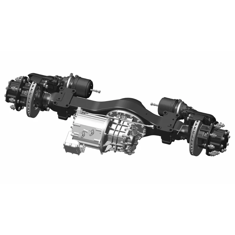
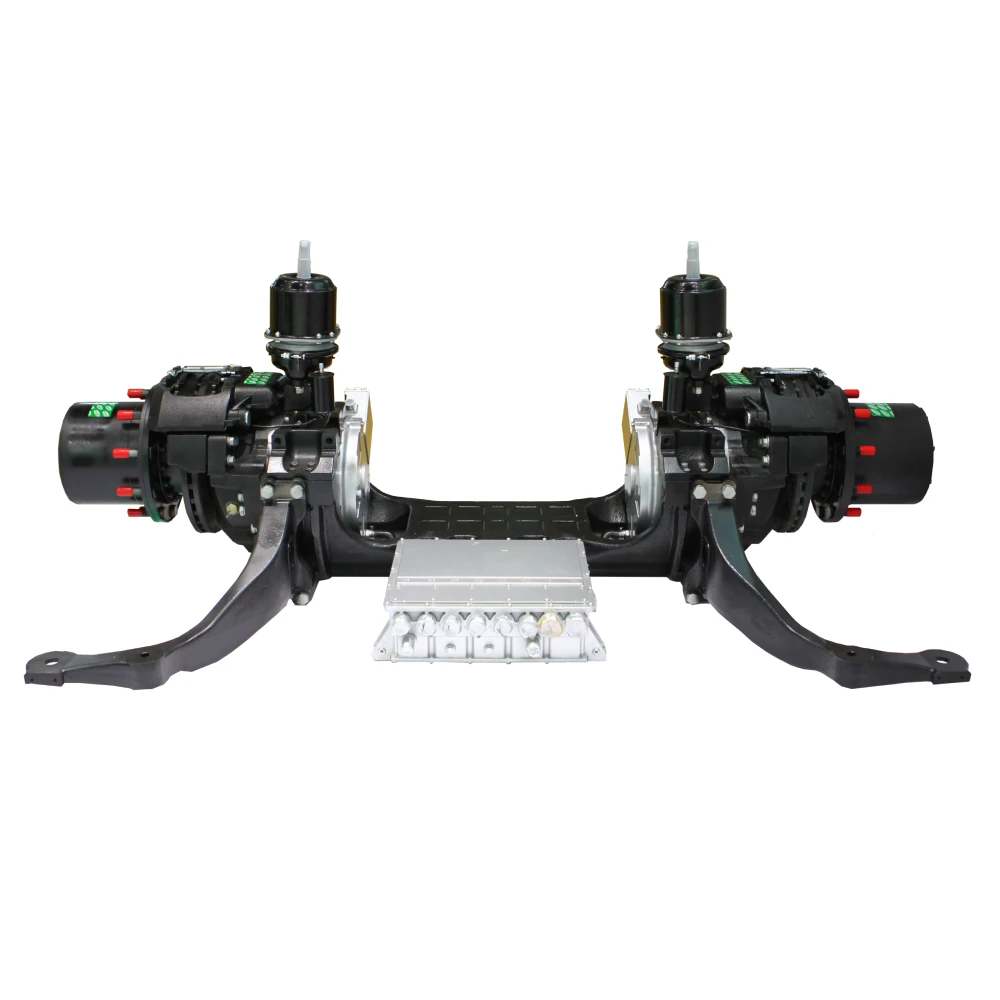
80kW / 160kW Electric Axle for Bus This 80kW / 160kW electric axle for bus integrates a high-speed electric motor, gearbox, and rear axle into a compact, lightweight system, optimizing both vehicle efficiency and chassis layout flexibility. Featuring a two-stage helical gear transmission, it achieves an impressive 70% energy recovery efficiency. By eliminating the driveshaft and spiral bevel gears, the system significantly reduces weight, further enhancing energy efficiency and overall vehicle performance. Whatsapp: +8619352173376 Email: contact@brogenevsolution.com Get Custom Quote Key Features of Brogen 160kW Electric Axle for Bus Compact Design The motor, gearbox, and axle utilize a highly integrated parallel-axis design, resulting in a lightweight system with high transmission efficiency. Improved NVH Performance The gearbox is engineered for all operating conditions, featuring in-house manufactured DIN 4-grade high-precision gears, ensuring low noise levels. Flexible Vehicle Layout By eliminating the driveshaft, the chassis provides additional space for battery placement, allowing for a more flexible vehicle layout. Technical Parameters The specific parameters vary depending on the configuration. For more details, please contact us: contact@brogenEVsolution.com Model OEEA85 Load 8500 kg Rim mounting distance 1838 mm (adjustable) Speed ratio 20.475 Maximum output torque 9214 N.m Type of hub bearing Maintenance-free Brake specification Pneumatic disc type 19.5″ Rated / Peak power 80 kW / 160 kW Rated / Peak torque 200 N.m / 450 N.m Rated / Maximum speed 3600 rpm / 12000 rpm Weight 525 kg More Power Options Model OEEA30 OEEA50 OEEA60 OEEA95 OEEA100 Load 3000 kg~ 3500 kg 4000 kg ~ 5500 kg 6000 kg 9500 kg 10000 kg Rim mounting distance 1605 mm (adjustable) 1760 mm (adjustable) 1515 mm (adjustable) 1916 mm (adjustable) 1832 mm (adjustable) Speed ratio 12.665 16.141 16.473 19.220 Gear 1: 55.2 Gear 2: 17.24 Maximum output torque 4433 N.m 5730 N.m 7412 N.m 14415 N.m 41400 N.m Type of hub bearing Maintenance-free Maintenance-free Maintenance-free Maintenance-free Maintenance-free Brake specification Hydraulic disc-type two-cylinder φ43 Pneumatic disc type 17.5″ Pneumatic disc type 17.5″ Pneumatic disc type 19.5″ Pneumatic disc type φ410 Rated / Peak power 65 kW / 120 kW 65 kW / 120 kW 80 kW / 160 kW 200 kW / 320 kW 200 kW / 320 kW Rated / Peak torque 160 N.m / 350 N.m 170 N.m / 355 N.m 235 N.m / 450 N.m 350 N.m / 750 N.m 350 N.m / 750 N.m Rated / Maximum speed 3580 rpm / 12000 rpm 3600 rpm / 12000 rpm 4100 rpm / 12000 rpm 4093 rpm / 12000 rpm 4093 rpm / 12000 rpm Weight 205 kg 255 kg 300 kg 583 kg 887 kg Brogen 160kW Electric Axle for Bus – Solution Advantages Central Direct Drive Powertrain for Bus Brogen Electric Drive Axle for Bus Higher Efficiency & Stronger Performance – A highly integrated two-stage helical gear transmission shortens the drivetrain, reduces axle load, and improves energy recovery efficiency by 10% compared to traditional central electric drive systems. Lightweight Design & Lower Energy Consumption – Removing the driveshaft and spiral bevel gears simplifies the system, significantly reducing weight and further enhancing energy efficiency. Improved NVH & Quieter Operation – Eliminating the driveshaft eliminates issues like shaft angles and dynamic balancing, reducing noise at the source for a smoother and quieter ride. Case Study – 8.5-meter City Bus As public transport operators face growing challenges and evolving industry demands, efficiency and service quality have become critical for sustainable operations. To meet these needs, a public transport company deployed the  8.5-meter battery electric city buses featuring our high-speed motor + high-speed gearbox + rear axle in an advanced 3-in-1 e-drive system.  Enhanced Safety & Reliability The axle head is welded using internationally advanced friction welding technology, ensuring superior strength and durability. The electric powertrain system has successfully passed a 1-million-kilometer durability test, guaranteeing long-term reliability for intensive daily operations. Optimized Space & Weight The integrated e-powertrain system reduces space usage by 25% and weight by 50% compared to conventional setups. The overall vehicle weight is reduced by 2,000 kg, cutting energy consumption by 10%, which extends driving range without increasing battery capacity. Improved Accessibility A single-step entry reduces passenger boarding and alighting time, improving operational efficiency. A fully flat floor design increases standing capacity, enhances layout flexibility, and eliminates interior steps, reducing step-related passenger injuries by 46%. Contact Us Get in touch with us by sending us an email, using the Whatsapp number below, or filling in the form below. We usually reply within 2 business days. Email: contact@brogenevsolution.com Respond within 1 business day Whatsapp: +8619352173376 Business hours: 9 am to 6 pm, GMT+8, Mon. to Fri. LinkedIn channel Follow us for regular updates > YouTube channel Ev systems introduction & industry insights > ContactFill in the form and we will get in touch with you within 2 business days.Please enable JavaScript in your browser to complete this form.Please enable JavaScript in your browser to complete this form. Name * FirstLast Work Email *Company Name *Your Project Type *– Please select –Car, SUV, MPVBus, coach, trainLCV (pickup truck, light-duty truck, etc.)HCV (heavy-duty truck, tractor, trailer, concrete mixer, etc.)Construction machinery (excavator, forklift, crane, bulldozer, loader, etc.)Vessel, boat, ship, yacht, etc.Others (please write it in the note)Your Interested Solutions *– Please select –Motore-AxleBatteryChassisAuxiliary inverterOBC / DCDC / PDUAir brake compressorEPS / EHPS / SbW / eRCBBTMSOthers (please write it in the note)Do you have other contact info? (Whatsapp, Wechat, Skype, etc.)Please introduce your project and your request here. * Checkbox * I consent to receive updates on products and events from Brogen, and give consent based on Brogen’s Privacy Policy. Submit

180kw electric portal axle from brogen
Industry Insight, Public Transportation, Technologies

110 kW / 180 kW Steering Electric Portal Axle for Bus With Independent Suspension

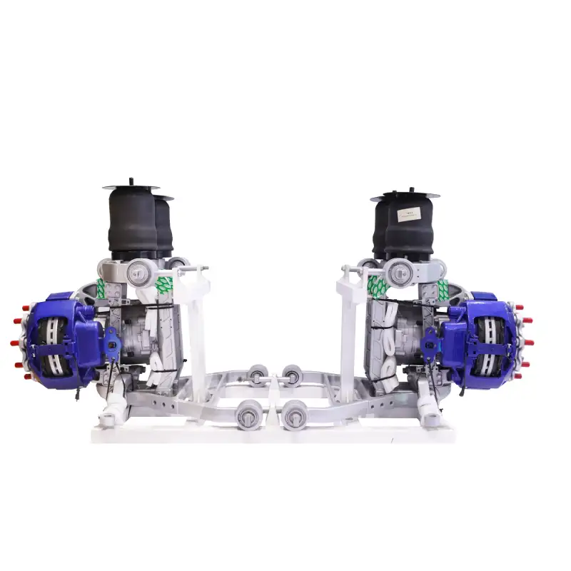
110 kW / 180 kW Steering Electric Portal Axle for Bus, Trolleybus This 110 kW / 180 kW steering electric portal axle is designed for public transport vehicles such as battery electric buses (BEBs) from 8 meters to 10 meters or trolleybuses. It adopts the distributed drive technology, allowing for precise torque and speed control of each wheel independently. Due to its unique features, this product enables highly customizable configurations for buses and provides passengers with greater convenience through its fully low-floor and wide-passenger aisle design. Whatsapp: +8619352173376 Email: contact@brogenevsolution.com Get Custom Quote Key Features of Brogen Electric Portal Axle Distributed Drive Adopts the distributed drive technology for the precise control of torque and speed of each wheel independently. Compact & Lightweight​ The compact layout integrates the motor, suspension system, and drive axle, reducing the need for complex components and space required by traditional drivetrains. Independent Suspension​ The four-airbag independent suspension structure results in lower noise and more stable steering. Technical Parameters Motor Type PMSM Motor Power (Rated / Peak) 2×55 kW / 2×90 kW Maximum Motor Speed 9500 rpm Motor Output Torque (Rated / Peak) 2×140 N.m / 2×350 N.m Rated Voltage 540 VDC IP Rate IP67 Axle Weight 850 kg Rated Axle Load 9000 kg Maximum Wheel Speed 540 rpm Gear Ratio 17.55 Rim Size 22.5 inch Tire Size 305/70R22.5 385/65R22.5 Brake Air disc brake Maximum Steering Angle ±18° Basic Structure The four-airbag double wishbone design offers reduced unsprung mass for a smoother ride with improved comfort and stability. With high torque and power density, the dual motors provide a strong and reliable output. The reducer  reduces the motor output speed to increase torque. The Motor Controller controls the motor to operate at the desired speed, angle, direction, and response time. Other Electronic Components: accelerator pedal sensors, brake pedal sensors, Hall-effect wheel speed sensors, Hall-effect steering angle sensors, roll angle sensors, yaw rate sensors, and controller hardware. Working Principle The VCU calculates the total torque demand based on the driver’s acceleration or deceleration intent.  The electric drive control unit (DCU) allocates the total torque between the left and right drive motors based on the steering angle, vehicle posture sensors, and road surface traction coefficients.  The left and right motor controllers (or 2-in-1 integrated motor controller), upon receiving the instructions, convert the energy from the battery to the necessary power for the drive motors, ensuring the vehicle’s stability and handling. Solution Benefits Low-Floor Design Adapts to the fully flat low-floor design and allows for easy one-step entry, providing a spacious aisle and reducing the risk of passenger falls. IP67 Protection An IP67 protection rating effectively prevents the intrusion of dust and water, providing enhanced performance in challenging conditions. Lower Maintenance Costs Utilizes maintenance-free wheel hub units, lowering maintenance costs. The advanced EDS ensures tire replacement intervals exceed 100,000 kilometers. Core Technology – Distributed Drive Electric Powertrain Traditional Electric Powertrain Solution Centralized Drive → Poor driving maneuverability Centralized Brake → Long braking distance Centralized Steering → Large turning radius Long Mechanical Transmission Chain Significant energy transmission losses; Poor applicability across vehicle models; Insufficient passenger space Distributed Drive Electric Powertrain Solution Drive / Brake Decoupling Distributed Drive → Enhanced control on complex surfaces Distributed Brake → Reduced braking distance on complex surfaces Distributed Steering Four-wheel Independent Steering → Reduces turning radius; enables lateral movement and zero-radius turns; significantly enhancing maneuverability Eliminates Mechanical Transmission → Increases user space; reduces energy transmission losses Our Projects Our distributed electric drive axle systems have been successfully implemented in city buses across Europe, the Middle East, Asia, and other regions. Incorporating advanced design concepts and control strategies, we prioritize the safety and reliability of our systems, delivering profitability for public transport vehicle manufacturers. Hydrogen buses with 320 kW eaxles Buses with the low-floor design Airport shuttle bus with 14T eaxles Pur electric buses with our eaxles Contact Us Get in touch with us by sending us an email, using the Whatsapp number below, or filling in the form below. We usually reply within 2 business days. Email: contact@brogenevsolution.com Respond within 1 business day Whatsapp: +8619352173376 Business hours: 9 am to 6 pm, GMT+8, Mon. to Fri. LinkedIn channel Follow us for regular updates > YouTube channel Ev systems introduction & industry insights > ContactFill in the form and we will get in touch with you within 2 business days.Please enable JavaScript in your browser to complete this form.Please enable JavaScript in your browser to complete this form. Name * FirstLast Work Email *Company Name *Your Project Type *– Please select –Car, SUV, MPVBus, coach, trainLCV (pickup truck, light-duty truck, etc.)HCV (heavy-duty truck, tractor, trailer, concrete mixer, etc.)Construction machinery (excavator, forklift, crane, bulldozer, loader, etc.)Vessel, boat, ship, yacht, etc.Others (please write it in the note)Your Interested Solutions *– Please select –Motore-AxleBatteryChassisAuxiliary inverterOBC / DCDC / PDUAir brake compressorEPS / EHPS / SbW / eRCBBTMSOthers (please write it in the note)Do you have other contact info? (Whatsapp, Wechat, Skype, etc.)Please introduce your project and your request here. * Checkbox * I consent to receive updates on products and events from Brogen, and give consent based on Brogen’s Privacy Policy. Submit

electric axle for bus (2) electric bus powertrain
Public Transportation, Technologies

Electric Bus Powertrain: Wheel-Side Drive Motor – Introduction and Analysis

Electric Bus Powertrain: Wheel-Side Drive Motor – Introduction and Analysis Electric buses have traditionally relied on centralized drive systems. Two main configurations have dominated the market: Direct-Drive Motor System In these systems, the electric motor directly replaces the internal combustion engine. This approach offers a simple and straightforward system architecture, with mature vehicle structural design technology that has made it the mainstream configuration for battery electric buses. Motor + Gearbox Systems This configuration, which combines an electric motor with an Automatic Manual Transmission (AMT) gearbox, delivers superior performance on steep slopes, meeting the demands of mountainous or scenic areas. Although it borrows extensively from conventional fuel vehicle technology and is relatively mature, including an automatic shifting mechanism can compromise reliability, leading to practical challenges in real-world operations. As electric bus powertrain systems evolve toward higher speeds, greater integration, and lightweight designs, distributed electric drive technology—exemplified by wheel-side drive motors—has begun to enter the practical stage. Compared with centralized drive systems, wheel-side drive configurations eliminate the need for transmission shafts, main reduction gears, and differentials. This results in a shorter power transmission chain, higher transmission efficiency, and a more compact structure.  In addition, precise control of wheel-side motor speed and torque enables integrated functions such as vehicle propulsion, braking, differential action, and energy recovery. Owing to its high degree of freedom and functional expandability, the wheel-side drive system has become a focal point in the research and development of pure electric bus powertrain systems. In addition, precise control of wheel-side motor speed and torque enables integrated functions such as vehicle propulsion, braking, differential action, and energy recovery. Owing to its high degree of freedom and functional expandability, the wheel-side drive system has become a focal point in the research and development of pure electric bus powertrain systems. Electric Bus Powertrain: Wheel-Side Motor Drive Configurations Wheel-side motor solutions for battery electric buses bridge the gap between centralized and hub motor designs. They typically integrate a motor with a fixed-ratio reducer mounted on the chassis, directly driving the wheels via short axles. Two primary configurations exist: A. Fixed-Motor Configuration The fixed-motor configuration usually takes the form of an integrated wheel-side drive axle. In this design, the conventional axle housing and half-shafts are eliminated, and the drive motor is mounted adjacent to the wheel. Despite maintaining a rigid axle structure, this design can employ either steel leaf springs or a combination of air springs and coil-over shock absorbers.  Brogen wheel-side drive system with fixed motors Key advantages: Reduced Weight and Space: By removing the axle housing, casing, and half-shafts, the overall structure is significantly lighter and more compact. High-Speed Motor Integration: With the use of high-speed motors paired with high reduction ratios (often through a planetary gear structure), the design minimizes motor volume and weight while increasing power density. Robust Performance: Our integrated wheel-side drive axle, for example, features two high-speed motors mounted on either side of the axle. With a two-stage reduction system, it delivers enhanced torque and is capable of handling high axle loads—ideal for heavy-duty, low-floor city buses. B. Swing-Motor Configuration In the swing-motor configuration, the traditional rigid axle is abandoned in favor of an independent air suspension system. Here, both the drive motors and reducers are mounted directly on the suspension, and the reducer can be designed as either a two-stage or planetary gear system. Brogen wheel-side drive system with swing motor and independent suspension Key advantages: Lower Unsprung Mass: The elimination of the rigid axle structure reduces unsprung mass. A well-designed suspension can effectively transfer the motor’s mass to the vehicle body, improving ride comfort and handling. Enhanced Cabin Design: This configuration enables increased interior space, a wider aisle, and lower floor heights—critical factors in the design of modern low-floor city buses. Benefits of Wheel-Side Drive Motors in Electric Buses The adoption of a wheel-side drive motor for an electric bus powertrain – where flexible electrical connections replace some mechanical linkages – offers significant benefits in electric bus design and performance. Below are the primary advantages:  1. Increased Cabin Space and Lower Floor Height Low-floor city buses are a growing trend. In these designs, the area from the front passenger door to the last axle forms a continuous, step-free zone. Lowering the interior floor not only reduces the number and height of steps – making boarding and movement inside the bus easier, safer, and more accessible for all passengers – but also increases headroom in key areas. For instance, the structural dimensions of an integrated wheel-side drive axle can reduce floor installation height by approximately 70 mm, achieving a floor clearance as low as 290 mm. This enhanced design meets both interior space and passenger safety requirements. 2. Vehicle Lightweighting Reducing the overall vehicle weight directly contributes to lower energy consumption. Research indicates that a 10% reduction in vehicle weight can lead to a 6% – 8% reduction in energy consumption. The wheel-side drive motor configuration achieves significant weight savings through: High-speed motor design: Increased motor speeds allow for lower torque requirements, which in turn reduces cost and weight. System integration: Consolidating components (motor, reducer, controller) into an integrated design reduces the need for additional attachments and cabling, thereby lowering both the weight and cost of the powertrain. 3. Enhanced Vehicle Dynamics Mainstream single-motor direct-drive configurations often struggle with steep climbs and mid-to-high-speed acceleration, while dual-motor systems face challenges in weight and cost. Additionally, motor+AMT configurations can suffer from power interruptions during gear shifts. In contrast, the wheel-side motor configuration: Dual-Motor Advantage: By deploying two motors, the power demand on each unit is reduced while maintaining overall system performance. Elimination of the Main Reducer: Replacing the main reducer with a high-reduction ratio gear system (using helical gears) not only simplifies the transmission patch but also improves strength, reduces manufacturing complexity, and lowers costs. 4. Improved Transmission Efficiency Eliminating the traditional main reducer and differential from the electric bus powertrain means that power is transmitted through a shorter chain – enhancing efficiency. The use of helical gears in the

e-axle with independent suspension
Public Transportation, Technologies

How an e-Axle with Independent Suspension is Transforming Electric Bus Design

How an e-Axle with Independent Suspension is Shaping the Future of Electric Bus Design? As the world shifts toward sustainable transportation, the demand for energy-efficient, high-performance solutions in electric buses and other Zero Emission Buses (ZEBs) is steadily increasing. One of the key innovations at the forefront of this transformation is the wheel-side e-axle with independent suspension system for public transportation electrification. This solution is reshaping the way we think about electric bus powertrains, improving overall passenger experience, and enhancing operational efficiency. The Next Level of Efficiency: Wheel-Side Distributed Drive E-Axle With Independent Suspension The wheel-side distributed drive e-axle with independent suspension system is designed to offer a lighter, more efficient, and more compact solution for EV buses. This technology effectively reduces vehicle weight and energy consumption. The result? More spacious interior, greater energy savings, and increased passenger capacity flexibility. Our e-Axle with independent suspension showcased at Automechanika Shanghai 2024 What sets this system apart is its unique design: the left and right wheel-side motors replace the traditional differential and gearbox, applying torque directly to the wheels. This not only simplifies the drivetrain but also minimizes energy loss, making the electric bus more efficient. The integration of high-speed motors and reducers ensures that the system delivers large torque in a small form factor, enhancing the vehicle’s power output. The wheel-side drive e-axle and its controller operate based on the same principles as the motor and controller systems used in other pure electric or hybrid buses. However, the key challenge in wheel-side distributed drive control for buses lies in achieving the differential speed function between the drive e-axles. As a result, the control strategy and functionality of wheel-side drive e-axles differ from those in other battery electric or hybrid buses. 1.1 Three Configurations of the ePowertrain System for Electric Buses The distributed wheel-side e-Axle solution eliminates the need for a differential, half-shaft, and shortens the transmission chain. This results in higher transmission efficiency, a lighter vehicle, and reduced energy consumption. The compact motor size and wide central aisle make it suitable for low-floor layouts. Before in-hub motor technology become fully mature, wheel-side distributed drive e-axles remain the best matching solution for electric buses. 1.2 Basic Structure of the Wheel-Side Distributed Drive e-Axle with Independent Suspension Independent Suspension System: Featuring a four-airbag double wishbone design, this system offers reduced unsprung mass, resulting in a smoother ride with improved comfort and stability. Dual Wheel-Side Motors: With high torque and power density, the dual motors provide a strong and reliable output. Reducer: Reduces the motor output power to increase torque. Motor Controller: Controls the motor to operate at the desired speed, angle, direction, and response time. Electronic Components: Includes accelerator pedal sensors, brake pedal sensors, Hall-effect wheel speed sensors, Hall-effect steering angle sensors, roll angle sensors, yaw rate sensors, and controller hardware. 1.3 Working Principles of the Wheel-Side Distributed Drive e-Axle with Independent Suspension At the heart of the wheel-side distributed drive e-axle system is the Vehicle Control Unit (VCU), which calculates the total torque demand based on the driver’s acceleration or deceleration intent. The electronic differential system allocates the total torque between the left and right drive motors based on the steering angle. vehicle posture sensors, and road surface traction coefficients. The left and right motor controllers, upon receiving the instructions, convert the energy from the battery to the necessary power for the drive emotors, ensuring the vehicle’s stability and handling. 1.4 Operating Modes of the Wheel-Side Distributed Drive e-Axle with Independent Suspension Driving Mode: The battery supplies energy to the drive motor through the motor controller, which then directly drives the wheels. Regenerative Braking Mode: The rolling wheels drive the motor (regenerative generation) to charge the battery (energy recovery). Applications of the Distributed Drive e-Axle With Independent Suspension on Electric Buses The wheel-side e-axle with 4-airbag independent suspension system is not just about technological innovation; it’s about transforming the way we experience and operate electric buses in urban environments. The system offers several key advantages: Increased Safety: With a low-floor layout, passengers, including the elderly, children, and people with disabilities, can easily board and disembark. The design also reduces the risk of accidents caused by falls on traditional steps, offering a safer and more inclusive experience for all. Enhanced Comfort: The independent suspension system significantly improves ride quality, with reduced vibration and a smoother overall journey. Improved Operational Efficiency: For an 8.8-meter electric bus, the weight of the e-powertrain system can be reduced by more than 700 kg; for a 10-meter electric bus, the weight of the e-powertrain system can be reduced by more than 800 kg, offering significant energy savings, improved range, and lower maintenance costs. Real-World Impact: Proven Performance The independent suspension e-axle has already been deployed successfully on electric buses in several countries. Statistics show that after one year of use of a city’s 200 units of electric buses, the passenger injury accident rate has dropped by about 70%, largely due to the elimination of high-step entryways and the vehicle’s stable ride quality. These buses are proving to be a safer, more efficient, and comfortable choice for city transportation. Advantages of our Electric Bus Powertrain Solution The wheel-side distributed drive electric axle system is a leading-edge solution for electric buses, offering a future-proof EV technology that enables operators to meet sustainability goals while improving passenger experience and operational performance. As the global market for electric buses expands, this innovation is paving the way for more sustainable, energy-efficient public transit systems in cities across the globe.  Optimized Interior Space – Enables an 800 mm wide aisle and a fully flat low-floor design for enhanced accessibility and passenger comfort. Enhanced Maneuverability & Safety – Integrated steering function allows the rear wheels to track the front wheels, significantly reducing right-turn accidents caused by wheel differences. Proven Reliability – Features a mature and dependable electronic differential system, with tire replacement mileage exceeding 100,000 km. Technical Parameters Item Parameters Motor type PMSM Motor power 2×55 kW / 2×90 kW Maximum motor speed 9500 rpm Motor torque 2×140