Concrete Mixer Electrification Project: Boost Fuel Efficiency & Reduce Costs
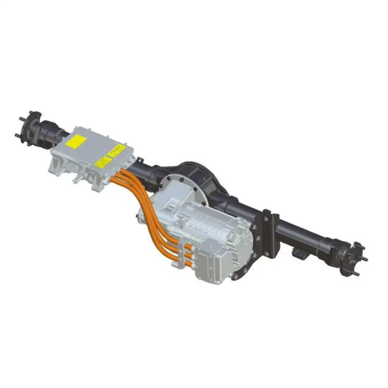
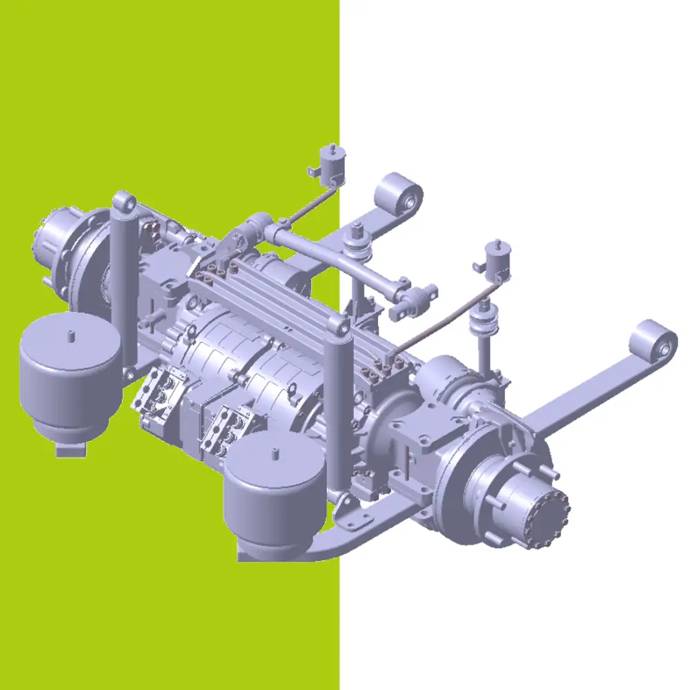
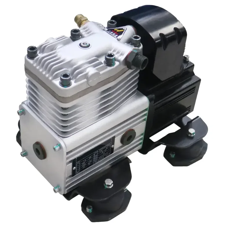
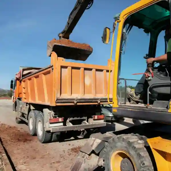
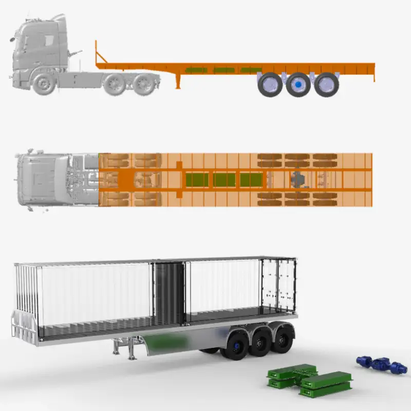
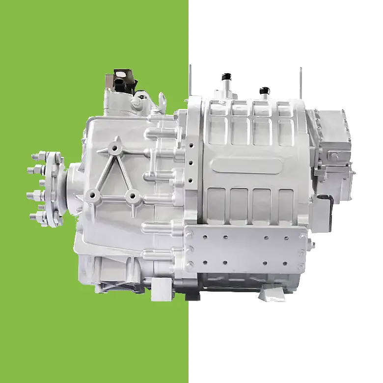
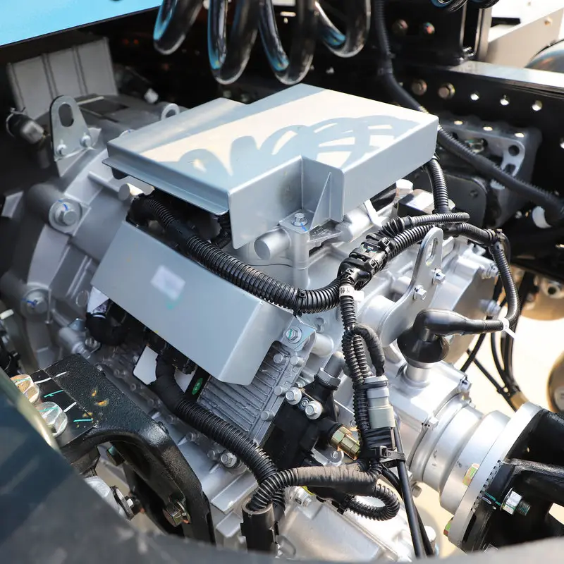
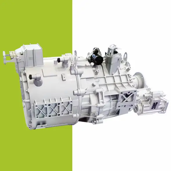
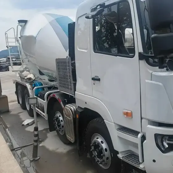
Concrete Mixer Electrification Project: Boost Fuel Efficiency & Reduce Costs Project Overview: Concrete Mixer Electrification In 2022, a concrete company approached us to implement a concrete mixer electrification solution for their fleet of 22 trucks. The goal was to reduce fuel consumption and improve operational efficiency by replacing the traditional hydraulic drum drive with a battery-powered electric system. Challenges in Concrete Mixer Operations Concrete mixer trucks face persistent challenges: High idling rates: 36%–70% of the operation involves idling while the mixing drum rotates. Extended operating hours: Trucks run 12–14 hours daily, but only half the time is spent driving. Excessive fuel consumption: The engine must stay on to keep the drum turning. Maintenance & engine wear: Continuous idling shortens engine life and increases maintenance costs. These challenges make concrete mixer electrification an ideal solution to save fuel and reduce operational downtime. Our Electric Drive Solution for Mixer Drums We implemented a battery-powered electric motor system to enable concrete mixer electrification. Key benefits include: Independent drum rotation: Onboard battery powers the drum during loading, unloading, or idle periods, allowing the engine to be turned off without interrupting drum operation. Energy-efficient loop: Surplus engine energy is captured to recharge the battery, minimizing power draw. Reduced fuel consumption: Eliminates unnecessary engine idling while keeping the drum rotating. Improved operation & comfort: Air conditioning and other vehicle systems remain fully functional during drum operation. Results & ROI from Concrete Mixer Electrification After almost a year of operation: Trucks achieved monthly fuel savings up to $1,000. Engine wear and maintenance requirements were reduced. Rapid return on investment: initial system costs expected to be recovered within months. This concrete mixer electrification project demonstrates how battery-powered drum drives can transform construction fleets—delivering fuel efficiency, sustainability, and reliable performance. Brogen EV Solution for Construction Machinery Electrification At Brogen, we provide customized EV solutions for construction machinery electrification, covering traction batteries, electric powertrains, and retrofit systems for various equipment, including concrete mixer trucks, mining trucks, e-trailers, tractors, cranes, and more. If you’re looking for an EV solution for your project, get in touch with us at contact@BrogenEVSolution.com to discuss your requirements. Contact Us Get in touch with us by sending us an email, using the Whatsapp number below, or filling in the form below. We usually reply within 2 business days. Email: contact@brogenevsolution.com Respond within 1 business day Whatsapp: +8619352173376 Business hours: 9 am to 6 pm, GMT+8, Mon. to Fri. LinkedIn channel Follow us for regular updates > YouTube channel Ev systems introduction & industry insights > ContactFill in the form and we will get in touch with you within 2 business days.Please enable JavaScript in your browser to complete this form.Please enable JavaScript in your browser to complete this form. Name * FirstLast Work Email *Company Name *Your Project Type *– Please select –Car, SUV, MPVBus, coach, trainLCV (pickup truck, light-duty truck, etc.)HCV (heavy-duty truck, tractor, trailer, concrete mixer, etc.)Construction machinery (excavator, forklift, crane, bulldozer, loader, etc.)Vessel, boat, ship, yacht, etc.Others (please write it in the note)Your Interested Solutions *– Please select –Motore-AxleBatteryChassisAuxiliary inverterOBC / DCDC / PDUAir brake compressorEPS / EHPS / SbW / eRCBBTMSOthers (please write it in the note)Do you have other contact info? (Whatsapp, Wechat, Skype, etc.)Please introduce your project and your request here. * Checkbox * I consent to receive updates on products and events from Brogen, and give consent based on Brogen’s Privacy Policy. Submit